H
HAYK

AD1856 DAC that should measure 0.0025%, in CD player is worst than Andrea's 200 ohm IV converter.
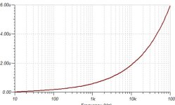
I located an image of Bernhard’s simple resistor I/V + filter circuit among my image collection. As I recall, Bernhard said the PCM56 distortion remains negligible even with higher value I/V resistors, such as shown below. Of course, the net in-band I/V resistance is only a little more than half that of the individual I/V resistors: So, 200R || (200R+33R) = 108 Ohms. Inductor L3 is to EQ the 3dB frequency response droop at 20kHz inherent to 44.1k sample-rate, NOS-DAC Zero-Order-Hold operation at that frequency.

Last edited:

@HAYK ,why don't you try something like this; discrete I/V
I'm not saying it's superb, but why not try it, normally you need to correct the values for a lower DAC current.
some useful information
I'm not saying it's superb, but why not try it, normally you need to correct the values for a lower DAC current.
some useful information
H
HAYK
Google search showed me many such iv converters, derived from CFA amp. topology.
As it is for audiophile use, I needed the minimum active components that are enrolled in conversion. This why I started with the Linear Audio magazine's proposition where only one transistor, MOSFET in my case, is the converter. The downside, the output impedance is high, 3.9k and needs capacitor coupling.
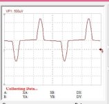
The suggested document doesn't know that the offset voltage, current is a major issue in R2R DACs. The AD811 with 3k feedback resistor has 500uv, a servo is a must.
The question of the thread remains unanswered, as bellow a certain value, it doesn't make any harm.
As it is for audiophile use, I needed the minimum active components that are enrolled in conversion. This why I started with the Linear Audio magazine's proposition where only one transistor, MOSFET in my case, is the converter. The downside, the output impedance is high, 3.9k and needs capacitor coupling.
The suggested document doesn't know that the offset voltage, current is a major issue in R2R DACs. The AD811 with 3k feedback resistor has 500uv, a servo is a must.
The question of the thread remains unanswered, as bellow a certain value, it doesn't make any harm.
Attachments
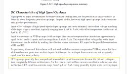
Maybe the document doesn't have anything about offset voltage, current, but it has a well-explained input impedance of various I/V stages and their impact on performance. For that reason I thought it might be useful.
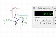
As for the AD811 with 1K in the feedback in my case I measured about 250uV offset, which is irrelevant for 4xPCM1702.
For audio DACs, I think that offset voltage, current is not so important as long as it is not specified in the DSs themselves. Normally it is meant to be as close to zero as possible.
Despite all the shortcomings I consider the AD811 the best choice for the I/V stage. At least for now😉
A simple I/V stage can be performed with a depletion mosfet, I drew something similar to a simple I/V stage with a lateral mosfet for TDA1541, but I never started to implement it. At that time, I was more involved with tubes for I/V.
H
HAYK
H
HAYK
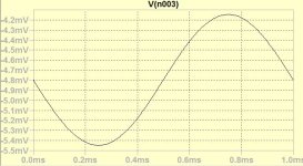
I simulated your circuit, it has -1.5mv offset showing the DACs.
If you add a resistor grounding the + input, you can cancel it.

If you add a resistor grounding the + input, you can cancel it.
By adding 1k resistor to the - input, the impedance is about 1 ohm, 0.7 for the LT1568, THS4011, opa1612. If the very low impedance has been increased, this means 0.7 ohm is the optimal value.
Attachments
It's time for you to build something and face the real world reaction , it may not be as the simulation says , nothing better than the real world , this is what DIY is all about 😉
.
.
H
HAYK
This is the Walt Jung's published article. The IV is intended for TDA1541 which has 25mv ac compliance. The 1k resistor is added because of the capacitor 2.2nF that Philips uses
as first pole of Bessel filter.
For R2R, it is better to keep the Rf alone and deal with post filtering.
For 15mohm, the PCB track should be low inductive.
as first pole of Bessel filter.
For R2R, it is better to keep the Rf alone and deal with post filtering.
For 15mohm, the PCB track should be low inductive.
Attachments
so it doesn't solder anything, it just simulates 😉It's time for you to build something and face the real world reaction , it may not be as the simulation says , nothing better than the real world , this is what DIY is all about 😉
.
H
HAYK
I made a quick trial with EF86 pentode instead of MOSFET.
V3 is 140v Vbe multiplier.

The input impedance is about 4ohms and the THD 0.004%. It might be suitable for TDA type switched current.
Those using 8x//AD844 with R2R, have 8ohms and they find much better than single AD844 60ohms and are happy with.
V3 is 140v Vbe multiplier.
The input impedance is about 4ohms and the THD 0.004%. It might be suitable for TDA type switched current.
Those using 8x//AD844 with R2R, have 8ohms and they find much better than single AD844 60ohms and are happy with.
As you said the man likes simulation and numbers , and what is suitable to TDA's , we have here an expert 😎so it doesn't solder anything, it just simulates 😉
.
H
HAYK
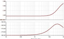
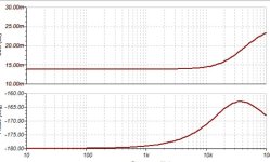
I found a dual CFA opamp of very low cost $2 that has 15mohm input impedance.

It is the headphone amp TPA6120.
Just add a TL072 as servo and you got a very low distortion IV converter for R2R.
It is the headphone amp TPA6120.
Just add a TL072 as servo and you got a very low distortion IV converter for R2R.
If a circuit is to be proposed, I'll start a new thread for it.It's time for you to build something and face the real world reaction , it may not be as the simulation says , nothing better than the real world , this is what DIY is all about 😉
The subject of this thread is to study the input impedance adequate for R2R.
H
HAYK
I found an ingenious floating OTA
Post in thread 'I/V and analog output stage for AD1862' https://www.diyaudio.com/community/...g-output-stage-for-ad1862.299414/post-4895077
As is it has an input impedance of 20 ohms . Modifying it I get 1.2 ohms and can go to 0.5ohms with 10 pair of transistors.
The distortion remains the same 0.06%.
I wonder what is the distortion of AD844 OTA.
Attachments

Last edited by a moderator:
H
HAYK
H
HAYK
I remembered that ltspice is allergic to floating supplies.
I modeled on Tina in Transnova topology. I read a distortion of 0.00002%.

I modeled on Tina in Transnova topology. I read a distortion of 0.00002%.
Here is something I was planning on the same lines, gave up as I moved on to discrete R2Rs.
Ofcourse it is not a fully completed circuit, Just the initial version. Jfet could be replaced with transistor to get similar results.

Thanks
Mallik
Ofcourse it is not a fully completed circuit, Just the initial version. Jfet could be replaced with transistor to get similar results.
Thanks
Mallik
- Home
- Source & Line
- Digital Line Level
- What input impedance for R2R I/V converter?