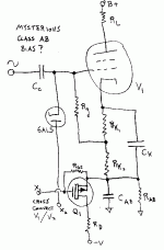
"I'm still not visualizing what this does in class AB push-pull and
how it stabilizes bias. .... Something I'm missing."
I also think the 6AL5 DC Restorer above is just fixing the DC blocking problem. The current thru the 6AL5 is telling us something though.
In keeping with the symmetry approach so far, I've added a Mosfet now to balance the auto bias during class B mode operation. The Mosfet tries to charge the Cab cap downward at the same rate that the tube charges the Ck cap upward during class B mode. (well, at half the rate, so that the mid point of Rk1 and Rk2 stays at constant voltage) Time constants of Ck/Rk1,2 and Cab/Rab would be the same, so that they can all relax back to class A conditions transparently. Cross connecting X1 and X2 is optional, but would give better tracking for assymetric signals.
Don
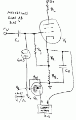
edit: Hmmm, on second thought, scratch this schematic, it needs to maintain constant voltage across Rk1, not relative to ground. A little re-arranging maybe......
Attachments
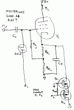
Simplified:
The Mosfets try to mimic the tube current during class B mode so that the voltage on Ck stays constant.
There should b an even better way yet. A switchable current mirror to throw the same tube current itself back at it, or just monitor the bottom of Ck for zero resultant current while in class B.
The Mosfets try to mimic the tube current during class B mode so that the voltage on Ck stays constant.
There should b an even better way yet. A switchable current mirror to throw the same tube current itself back at it, or just monitor the bottom of Ck for zero resultant current while in class B.
Attachments
Michael Koster said:
I'm not sure I follow but you seem to be saying that I have the
semantics of a P-tube wrong and the control signal should reference
the P-anode, but that's why I call it a P-cathode; because it is the
origin of the imaginary p-hole space charge. Or positron space charge...
So it looks like my original P-MOStrode got everything backwards
except the zener diode
Michael
I think "source" "drain" "collector" and "emitter" refer to carriers,
and may flip with carrier type. Anode & Cathode are terms specific
to electrons only. Or maybe I am confused? Whatever...
Anyways, I see you use a low impedance voltage follower to
inject the signal into the feedback divider. While I've drawn a
high impedance voltage controlled current source to perform
the same function.
Its obvious the Fetron/Mostake/Discombobulatrode must be
the device on the right along with its Schade network. The
other device on the left merely buffers the input to a higher
tubelike impedance. Also preventing impedance fluctuations
of the drive from mucking with the computation of Mu.
I recall seeing a demo of a solid-state device purported to 'faithfully emulate all aspects of a triode' So of course I walked up to the circuit and gave it a little tap...HMM, NOPE, cuz on guitar amps that mechanical pickup is a very important aspect of the toob 'crunch'.
Schaded FET?
Why not?
It has capacitive input impedance and non-linearities, so capacitive Shade-type feedback would be what the doctor prescribed.

eh? FET where, at the OPAMP inputs?
JFET I should have been more specific.
What's the difference? It has capacitive input as well, even though capacitance is lower. And yes, this amp should use Scott Wurcer's super-fast OpAmps he gave me on BAF 2 years ago, they have JFET inputs. 😉
Thanks for the sketch. I think you would want to buffer the input in case of the use of a tube or passive preamp where the impedance to the input is high.
Why not?
It has capacitive input impedance and non-linearities, so capacitive Shade-type feedback would be what the doctor prescribed.

I think you would want to
No, I would not.
10K input impedance on 20 KHz is more than plenty.
- Status
- Not open for further replies.
- Home
- Amplifiers
- Tubes / Valves
- What if O.H. Schade had MOSFETs?


