Answer:
The result is a Chtringlunator
The Tringlotron
The Regulator-Chip Amp
And their progeny: the Chtringlunator is a headphone amplifier, capable of delivering 500mW into 32ohm at low distortion, and without overall negative feedback.
The minimum power supply voltage required to obtain this power is 21V.
Pics will follow
Attachments
Member
Joined 2009
Paid Member

I run on pure, high quality biofuel, and there is not one square centimeter of carpet left in my home.
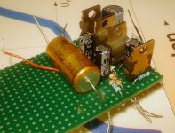
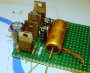
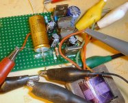
Here are the pictures of the prototype and the test set-up.
Measuring the THD proved quite challenging, not only because it is very low, and the circuit is a bit noisy, but also because the output is floating.
I had to use a 1:1 transformer, which served to subtract the output from the input.
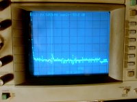
With 12Vpp input, the residue caused by phase shifts, imperfections in the amplifier and transformer was 70mVpp. That's 44.5dB down.
The residue was measured on a spectrum analyzer (I didn't include a screenshot of the output waveform, it is just a boring sinewave).
The dominant harmonic is the third (cursor), at -53.3dB.
The global THD is about -51dB. Taking the subtractor into account, this put the actual THD at -95dB or 0.0018% (18ppm).
This is quite surprising, because the sim predicted a much higher figure of 0.0080%, and moreover, this figure also includes the distortion of the test transformer, which is subjected to the full amplitude of the signal.
This means the actual figure is even lower, particularly for the odd components.
The Tringlotron topology is basically asymmetric, and tends to produce more even harmonics.
The transformer is a very high quality one, salvaged from a professional Philips equipement, but it certainly contributes significantly to the THD figure.
The true distortion of the Chtringlunator is probably under 10ppm, and this is at the max power of 500mW.
At more reasonable levels, it is even lower.
Here are the pictures of the prototype and the test set-up.
Measuring the THD proved quite challenging, not only because it is very low, and the circuit is a bit noisy, but also because the output is floating.
I had to use a 1:1 transformer, which served to subtract the output from the input.
With 12Vpp input, the residue caused by phase shifts, imperfections in the amplifier and transformer was 70mVpp. That's 44.5dB down.
The residue was measured on a spectrum analyzer (I didn't include a screenshot of the output waveform, it is just a boring sinewave).
The dominant harmonic is the third (cursor), at -53.3dB.
The global THD is about -51dB. Taking the subtractor into account, this put the actual THD at -95dB or 0.0018% (18ppm).
This is quite surprising, because the sim predicted a much higher figure of 0.0080%, and moreover, this figure also includes the distortion of the test transformer, which is subjected to the full amplitude of the signal.
This means the actual figure is even lower, particularly for the odd components.
The Tringlotron topology is basically asymmetric, and tends to produce more even harmonics.
The transformer is a very high quality one, salvaged from a professional Philips equipement, but it certainly contributes significantly to the THD figure.
The true distortion of the Chtringlunator is probably under 10ppm, and this is at the max power of 500mW.
At more reasonable levels, it is even lower.
Attachments
Some further details:
Unlike the class B regulator chip amp, this one has no slew-rate issues: it can provide its full power on the whole audio spectrum, and well beyond.
And though its performances are no better than a discrete tringlotron, they are much less dependent on accurate matching and thermal tracking of the output devices.
Member
Joined 2009
Paid Member
The golden question - how does it sound ?
I'm afraid I'm the least qualified individual to answer that question, because,
a) I have tin ears,
b) I am the creator of the circuit, and therefore I cannot be objective on the subject. It's like asking a man if he is a good lover or a good driver 😀
I will just venture so far as to say it sounds normal...
For the rest, you'll have to build one for yourself.
How easily can this be changed to an I-V converter with zero impedance input - I'm thinking of something to use as output stage for a Sabre DAC?
I see John Broskie has done his own config - a Triadtron & used it as I-V
I see John Broskie has done his own config - a Triadtron & used it as I-V
This topology cannot be used as such for that purpose.
But the tringlotron principles can be applied to an I/V converter.
Here is an example: it is not very elaborate, and the performances are modest, but it shows the way.
With some minor modifications, the transistors could be replaced by voltage regulators.
But the tringlotron principles can be applied to an I/V converter.
Here is an example: it is not very elaborate, and the performances are modest, but it shows the way.
With some minor modifications, the transistors could be replaced by voltage regulators.
Attachments
You say headphone amp? See this:
24V Aikido Line Stage and Headphone Amplifier
I use Broskie's LM317 output stage with different tube stage, and powered tube heater with lower LM317 in the same time.
I can't say it sound "normal", it sound really good!
24V Aikido Line Stage and Headphone Amplifier
I use Broskie's LM317 output stage with different tube stage, and powered tube heater with lower LM317 in the same time.
I can't say it sound "normal", it sound really good!
Well, there's nothing new under the sun: I wasn't aware Broskie had used regulators in this way.
Greetings Elvee,
I'd first like to thank you for all the work you had put in to designing with regulator output stages!
However I am having trouble wrapping my head around this circuit.
Being headphones the ground return pins are tied together. Does this imply that each channel would each utilize 3*LM317 wired in Tringlotron, but both return to a common constant current sink at the bottom?
Also, would it be possible to wrap all this within the feedback loop of an opamp to further reduce distortion similar to that you've done in the SE class A version?
You need 2*(3*LM317), and you must keep the two channels completely separate (no common sink).However I am having trouble wrapping my head around this circuit.
Being headphones the ground return pins are tied together. Does this imply that each channel would each utilize 3*LM317 wired in Tringlotron, but both return to a common constant current sink at the bottom?
This means you have to untie the ground return connections of the two earpieces.
This would not be impossible, but it would be pretty difficult, because the op amp should be wired to accept the feedback in balanced mode.Also, would it be possible to wrap all this within the feedback loop of an opamp to further reduce distortion similar to that you've done in the SE class A version?
In practice, this probably means that two opamps would be required: one as the gain element, and one as a balanced to SE converter.
And it is probably not worth the trouble, since the Tringlotron structure already has a good degree of distortion cancellation by itself, without any NFB.
Oops!
Including the current sinks, you need 2*(4*LM317), of course.
Altough in theory a single current sink with two balancing resistors would suffice, but it is better to keep the channels completely separate.
Including the current sinks, you need 2*(4*LM317), of course.
Altough in theory a single current sink with two balancing resistors would suffice, but it is better to keep the channels completely separate.
Last edited:
I've been plowing through a tubecad article and now I might be understanding the tri-tron a bit better. I guess it can almost be seen as a discrete differential to balanced driver of some sort?
Unfortunately I am not ready to re-cable all my headphones, and can't try out this design, for small speakers maybe.
Would your regulator chip adaptation for JLH topology perhaps be a better candidate for regular headphones? This one I have more trouble understanding but intuitively I think this also needs to have separate return leads for stereo, but JLH was a headphone amp afterall.
I am really into the idea of using regulators because I have a bunch of them lying around, and there is little chance for thermal runaway like transistors, running adequately low quiescent current without heatsinks even!
I am looking for advice on which regulator circuit to build before I go into the simple cap-coupled LM317 as emitter follower + CCS wrapped around opamp NFB, but I already had one built like this with transistors. Does anyone have any suggestions for more "fun" single supply circuits?
Hmm, not really. It requires a balanced (=floating) load to inject an antiphase distortion signal into the return wire, but calling that balanced would be an abuse of languageI've been plowing through a tubecad article and now I might be understanding the tri-tron a bit better. I guess it can almost be seen as a discrete differential to balanced driver of some sort?
I can understandUnfortunately I am not ready to re-cable all my headphones, and can't try out this design, for small speakers maybe.
It would, but for a stereo headphone amp the SE version is probably the best choice: it offers two channels with only three chips, and is quite unusual too.Would your regulator chip adaptation for JLH topology perhaps be a better candidate for regular headphones? This one I have more trouble understanding but intuitively I think this also needs to have separate return leads for stereo, but JLH was a headphone amp afterall.
I used it as my headphone amp for a time, and boy, oh boy! It does deliver.
I had to quit before my eardrums were completely burnt off, but it was like leaving an addiction for some hard stuff.
Yeah, that's my idea too: with regulators, you have the flexibility of discretes combined with the performance and safety of a chip. A real winner.I am really into the idea of using regulators because I have a bunch of them lying around, and there is little chance for thermal runaway like transistors, running adequately low quiescent current without heatsinks even!
Pardon my language.
When I first looked at the SE class A I was under impression that since 2 channels are have different potentials, each had to be referenced to different rails if single supply was used.
But it just occurred to me that this made no sense at all! I'd be able to flip polarity on the lower output cap and reference both channels to V-, is that right?
Since I am coming from a single supply (have to many laptop PSU lying around), I'd be using either a TLE2426 rail splitter for input ground or a equal value resistive splitter, but would it make more sense if some uneven resistor divider was used to set the opamps' output differently in the first place?
I am not familiar with introducing DC to the inverting input, but it looks like 390k+10k || 100k divider would provide 4.8V from the rails. This looking rather close to the rails so I may be wrong.
- Status
- Not open for further replies.
- Home
- Amplifiers
- Chip Amps
- What happens when you cross a Tringlotron with a Regulator-Chip Amplifier?