Cheers!
I've got a punch of these low price 5" bass drivers and I want to design a suitable sub for these cheap woofers.
Do you have any recommendations for me referring to the enclosure type to get a serious low end out of these 5"?
Here are the TSP:
fs = 72,6 Hz
Re = 7,5 Ohm
Qes = 0,41
Qms = 2,37
Qts = 0,35
Vas = 5,25 L
Cms = 0,47 mm/N
Mms = 10,13 g
Sd = 88 cm²
BxL = 9,2 N/A
Rms = 1,9 kg/s
Le = 1,77 mH
I was thinking of some type of bose 8th order bandpass style would do the job, but I would prefer something hornloaded ( i.e. TH/RLH or compound horn style).
Thx in advance for your help!
gzg
Horn loading might work (not my area of expertise), but a sealed box with eq would work, especially if you have a lot of the drivers. What are the size limitations?
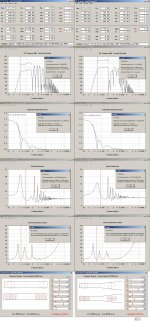
Here's a tapped horn design, and tweak in horn resp as desired. The throat size is too small, so my suggestion would be to use a multiple of drivers (say 2), and increase all the cross sectional areas by that number.
I don't know what X max is but I managed to drag response down to 40 Hz (about an octave below driver Fs) where you're Xmax limited to 5 watt input per driver . SPL at that point is about 105 - 110 db, with room gain flattening out the response.
I don't know what X max is but I managed to drag response down to 40 Hz (about an octave below driver Fs) where you're Xmax limited to 5 watt input per driver . SPL at that point is about 105 - 110 db, with room gain flattening out the response.
Attachments

Do you have any recommendations for me referring to the enclosure type to get a serious low end out of these 5"?
Greets!
It will take ten drivers to = a 15", though with only 2-3 mm of usable excursion at best and with a ~15 Hz low cutoff capability (FL) you'll have to define 'serious' to see if you have enough drivers to go low with any authority.
GM
Thank you for your replies!
Of course, my intension was to use multiple drivers in a single enclosure, let's say about 8 pieces. I was thinking of an push-pull arrangement as well, like in danley's DTS-10, to avoid linear harmonic distortion caused by the motor and to get a better cone control due to less excursion.
To get the smallest excursion as possible I thought a TH design would be the best choice. What do you think?
Unfortunately I don't know the Xmax of the driver and I realy don't know what the driver is capable to do. Power ratings are 90W continous/180W programm.
What about these bose type woofers in the acoustimas sub modul? I always thought that they are small and offer a small Xmax as well or am I wrong?
That's why I first was thinking to suit my 5" drivers in a bose style bandpass enclosure... would you disadvise me to design something similar?
Size limitations of the whole enclosure would be about ~500L brutto.
Wow, the TH design looks quiet good!
I got the chance to take measurements of the voice coil and the pole plate to caculate the linear excursion of the driver. Here you are:
Magnetic Gap Depth = 5.25mm
Voice Coile Winding Depth = 10.5mm
I would assume that Xmax would be 2.5mm in one direction...?
Would be interesting to see where the output of the TH is limited by the excursion.
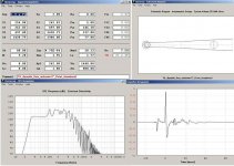
Here is a tapped horn with throat chamber coupled to horn.
why did you implement a chamber between the driver and the throat?
is there a reason to port the chamber with an offset into the horn and not at the beginning of the TH?
Hi Ibex,
I added the throat chamber as an option, and to minimize the L12 distance. Shortening L12 strongly affects the impulse response. Without knowing the rough external dimensions desired this looked like a reasonable first stab at a simulation.
As to the Xmax, even if you add half the gap depth you don't come anywhere close to what you would like to see in a driver build for subwoofer duty (see Post #4 by GM).
Regards,
I understand what you mean and I know that these drivers aren't well suited for a sub application, regardless I would like to try to get the maximum out of them and to find the most efficient enclosure for such a "unusual subwoofer driver".
How knows what those bose type acoustimass drivers are able to do, what excursion are they capable? Isn't it, that bose squeezes an amount of low end and spl out of some low pricey drivers as well? Or am I completely wrong with this presumption?
gzg
How knows what those bose type acoustimass drivers are able to do, what excursion are they capable? Isn't it, that bose squeezes an amount of low end and spl out of some low pricey drivers as well? Or am I completely wrong with this presumption?
gzg
I would assume that Xmax would be 2.5mm in one direction...?
Would be interesting to see where the output of the TH is limited by the excursion.
(10.5-5.25)/2 = ~2.63 mm, so the 3 mm I used is close enough for an acceptable distortion limit.
Input it into Oliver's design to find out and play with the Wizard to find an acceptable trade-off between LF extension, mid-bass 'punch' capability and boundary loading.
GM
Would you suggest to use a TH for maximum efficiency and low end in combination with such an unsuitable driver or would you recommend me to choose another enclosure type?
How knows what those bose type acoustimass drivers are able to do, what excursion are they capable?
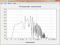
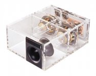
They 'squeeze' two or three cheap drivers very hard in a narrow BW 6th or 8th order BP (TP, TH, TTQWT, Karlson K15 are 8th order) and EQ it to suit:
Bose AM-15
BASS MODULE
F3 = 280/220 Hz
F6 = 46/40 Hz
Response measured with 2.8 volts of pink-noise input.
GM
Attachments

Would you suggest to use a TH for maximum efficiency and low end in combination with such an unsuitable driver or would you recommend me to choose another enclosure type?
Short of a large walk-in closet size (if folded) FLH (~13 k L for a ~20 Hz compression horn), the TH is your best best overall AFAIK. I mean ~500 L corner loaded and tuned to ~15 Hz combined with ~10 W will in theory allow live rock concert levels from ~40 Hz-up and ~2 W gets you DD/DTS/THX reference to 20 Hz if a steep high pass is used, so loud enough AFAIK for all but a few uncompressed recorded sounds such as a space shuttle launch.
GM
Hi Ibex,
I like the tapped horn approach, but you should first refine your application data. Is it for the home? Would couch risers a la TH-SPUD be what you are looking for, how about multiple subs (e.g.: 4 or more subs for one room), what about subs that double as speaker stands for the main L/R?
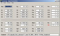
Here is one more simulation that will need a very solid room corner: 500 Liter net; if the Re is 7.5 Ohm this would probably qualify as a 10 Ohm speaker, let's see 100W into 10 Ohm and SPL response above 130dB with 3.5mm excursion @ 30Hz. That sounds pretty cool.
Regards,
I like the tapped horn approach, but you should first refine your application data. Is it for the home? Would couch risers a la TH-SPUD be what you are looking for, how about multiple subs (e.g.: 4 or more subs for one room), what about subs that double as speaker stands for the main L/R?
Here is one more simulation that will need a very solid room corner: 500 Liter net; if the Re is 7.5 Ohm this would probably qualify as a 10 Ohm speaker, let's see 100W into 10 Ohm and SPL response above 130dB with 3.5mm excursion @ 30Hz. That sounds pretty cool.
Regards,
Attachments
Thanks tb46 for your help!
The sub should be as followed:
WxHxD: 1230 x 400 x 600 mm
It should utilize the power of 8 of these tiny drivers (or more if desired), only one sub should be used.
It is intended to use it in a home theater application.
No couch raisers, more like a center speaker/hifi-rack raiser.
The sub should be placed between the mains directly underneath a wall mounted LCD screen infront of a wall. The solid wall is 3.5m wide and may act as an horn extension where the mains are placed, probably the horn mouth should emit on the left and on the right of the sub enclosure to have a better corner loading...? (optional placing the horn mouth on the front)
gzg
Hi Ibex,
So you are looking for something with the old Isophon/Klason form factor, nice project. That will be a challenge to fold:
http://www.diyaudio.com/forums/subwoofers/100295-klason-strange-folded-basshorn-acient-design-4.html
Regards,
So you are looking for something with the old Isophon/Klason form factor, nice project. That will be a challenge to fold:
http://www.diyaudio.com/forums/subwoofers/100295-klason-strange-folded-basshorn-acient-design-4.html
Regards,
Hmm... never have seen this Klason & Strange design before.
Looks interesting, but my intension was to have the exits on the left and the right side of the enclosure near the wall behind and the floor to archieve a 1.0xPi loading, if necessary. Or would the boundary at the back of the enclosure affect the output as well, if the horn exit is placed on the front of the cab (~60cm distance to the wall)?
Looks interesting, but my intension was to have the exits on the left and the right side of the enclosure near the wall behind and the floor to archieve a 1.0xPi loading, if necessary. Or would the boundary at the back of the enclosure affect the output as well, if the horn exit is placed on the front of the cab (~60cm distance to the wall)?
- Status
- Not open for further replies.
- Home
- Loudspeakers
- Subwoofers
- What enclosure type for this cheap trick driver?