Hi,
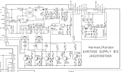
To start the sequence you need to enable Q456 by applying a positive voltage to the base. This will enable Q455 > enable Q454 >Q455 will delay and then Q453 will enable relay 452. If you have a positive voltage at the Q456 then
the emitter will be positive.
To start the sequence you need to enable Q456 by applying a positive voltage to the base. This will enable Q455 > enable Q454 >Q455 will delay and then Q453 will enable relay 452. If you have a positive voltage at the Q456 then
the emitter will be positive.
I think you can do a test by removing 458 connector and with a 1K resistor momentary jump 4 and 1 and all relays should pickup. If everything it is OKAY.
Hi,
The problem we were looking for 5 volts at pin 2 it is that for the micro to see a logical one the voltage should be 3 volts or higher. Below 3 it can be a zero. The micro it is the one that enable the relays by sending a signal to enable the relays. I am not sure if for the micro to enable the relay it need pin 2 high. That is why we are looking a 5 at pin.
I would not design a power monitor the way you said.
By the circuit shown in the schematic Pin2 is supposed to have a saw-tooth wave form with a flat top at 5V, and a bottom can be as low as near 1V. I don't know what circuit in the micro board looks like, but if I was the designer i'd feed this wave form into an NPN transistor inverter's base, when the mains power is good, this transistor always saturates and outputs a logic 0.
C465 is charged to 5V by the positive cycle of AC, and is discharged by R454 between charge cycles. The time constant of C465*R454 makes sure as few as one missing charge cycle will cause C465 be dicharged to below the threshold of the NPN transistor inverter, causing a logic "1" at its out put. This is supposed to be a very reliable power failure detector and it has a maximum response time of 16.7 mS.
Last edited:
Hi,
What you said it is true but I am looking in the way the micro see a logic zero or a one to determine the status of the signal. There is two way a micro can read the signal logically or analog. If the micro has an A/D it will read like you said because you can set setting from 0 to 5. Now logically it is different. To read zero it is between .5 and 2.75 high it is from 3.75 to 5 volts. How method they are using that it is the question to solve. Logically 2.78 can be a zero or 1. Analog no problem.
What you said it is true but I am looking in the way the micro see a logic zero or a one to determine the status of the signal. There is two way a micro can read the signal logically or analog. If the micro has an A/D it will read like you said because you can set setting from 0 to 5. Now logically it is different. To read zero it is between .5 and 2.75 high it is from 3.75 to 5 volts. How method they are using that it is the question to solve. Logically 2.78 can be a zero or 1. Analog no problem.
Hi,
What you said it is true but I am looking in the way the micro see a logic zero or a one to determine the status of the signal. There is two way a micro can read the signal logically or analog. If the micro has an A/D it will read like you said because you can set setting from 0 to 5. Now logically it is different. To read zero it is between .5 and 2.75 high it is from 3.75 to 5 volts. How method they are using that it is the question to solve. Logically 2.78 can be a zero or 1. Analog no problem.
My circuit does not need an A/D. The inverter outputs logic levels.
2.78VDC is just an average of that sawtooth waveform shown on a multimeter when one choose to measure with. It tells very little by itself if not nothing. And I'm quite sure an engineer will not feed a sawtooth into an A/D in a consumer electronics micro for a purpose of power failure detection in a real world. There are so many other ways to do it, far simpler and far more reliable and straight forward. An NPN transistor inverter following pin2 is a good example that reliably and quickly provides a logic 0/1 when AC power is good/failure.
Srinath, can you post the schematic showing the circuit around the micro, on the other side of CP458? it should give a bigger picture and help understand the operation of the power board and its controls.
Hi,
I agreed 100% with you but remember some time companies short cut to save in cost. Normally I will use what you just described. A simple transistor will give a cleaner signal but it will cost a transistor.
I agreed 100% with you but remember some time companies short cut to save in cost. Normally I will use what you just described. A simple transistor will give a cleaner signal but it will cost a transistor.
I'll post the schematic - It may take a bit, I am on my son's laptop, and the schematic is on my laptop, which is currently dead.
Just gimme a day or 2. Thanks you 2, I was so glad 1 person was looking at this problem ... now 2 ... thanks.
Cool.
Srinath.
Just gimme a day or 2. Thanks you 2, I was so glad 1 person was looking at this problem ... now 2 ... thanks.
Cool.
Srinath.
Finally getting back to this - life gets in the way, then you forget.
Anyway I had pretty much traced the problem to a bad soft start board transformer.
T451 in this diagram. The secondary tested like a capacitor, showing a resistance and promptly flipping to open.
Can I get a generic soft start board off ebay ? Or get one of those and pull the transformer off it.
Or a small transformer -
Thanks.
Srinath.
Attachments
Hi,
Check this power transformer in Mouser. Mouser part number 838-3FS-516.
See if the pins are compatible with your board. The transformer it is 16 volts and .800 amps. The relays are 12 volts dc. I think you can use this transformer with no problem or if you have space you can buy one with leads and solder the wires in the boards eyelets for the transformer.
I'll check that part.
but I believe I have a 10.7 or so ac voltage transformer out of a CT-F 2121 tape deck that would have to be fitted to the top of the big transformer soldered into it. I am considering making a plug for it and trying to see if it will power up.
Now isn't 16v ac a little excessive.
Thanks.
Srinath.
but I believe I have a 10.7 or so ac voltage transformer out of a CT-F 2121 tape deck that would have to be fitted to the top of the big transformer soldered into it. I am considering making a plug for it and trying to see if it will power up.
Now isn't 16v ac a little excessive.
Thanks.
Srinath.
Hi,
If you think it is too high then go to the 838-3FS-412. This one the output voltage it is 12.6 volts. The 3 relays are 12 volts DC.
If you think it is too high then go to the 838-3FS-412. This one the output voltage it is 12.6 volts. The 3 relays are 12 volts DC.
The transformer may be only 9Vac.
After the bridge rectifier it will give anywhere from 11Vdc (fully loaded) to 15Vdc(lightly loaded)
After the bridge rectifier it will give anywhere from 11Vdc (fully loaded) to 15Vdc(lightly loaded)
The transformer I have is out of a tape deck. It has something like a 3-4 amp capacity. I have to check. Its 10X the size of the original cheese cube that was there.
Now we are triggering 12v relays - and would we need any more than 12-13v under load to do so ? I already have this, and I even have it soldered in, I just haven't had the time to connect and power up.
I hope it works, it would save me buying the transformer.
Also that old transformer, what caused it to fail is another thought.
Cool.
Srinath.
Hi,
Which winding was open? Sometime some manufacture installed a small thermal fuse in the primary. If the transformer get hotted the fuse will open permanently and need replacement.
Which winding was open? Sometime some manufacture installed a small thermal fuse in the primary. If the transformer get hotted the fuse will open permanently and need replacement.
I believe secondary was open, I dont recall I will read through my old posts its been 6 months. I will check to be sure.
Now here is another stupid question.
Can I use something like this - if my tape deck idea doesn't pan out.
AC 110V to 12V Power Converter Low Voltage Electronic Transformer | eBay
Thanks.
Srinath.
Now here is another stupid question.
Can I use something like this - if my tape deck idea doesn't pan out.
AC 110V to 12V Power Converter Low Voltage Electronic Transformer | eBay
Thanks.
Srinath.
Hi,
I tried one and it didn't work. DOA. I will not use it. If you really want to try one you can buy one in Radio Shack. Sometime in an emergency I go to Radio Shack and buy one. They are pricey but you can finish your project right away. Also you can use a wall type transformer only for a test.
I tried one and it didn't work. DOA. I will not use it. If you really want to try one you can buy one in Radio Shack. Sometime in an emergency I go to Radio Shack and buy one. They are pricey but you can finish your project right away. Also you can use a wall type transformer only for a test.
The advantage of that was that I could use 2 sided tape on it and glue it to the top of the main trafo. The tape deck trafo is too heavy to sit there reliably with just 2 sided tape.
Cool.
Srinath.
Cool.
Srinath.
Hi,
I think the best option it is the transformer from Mouser. You may be able to bent the pins to fit the holes in the printed board. Remember do it right the first time. Do not try to cut corner or you will paid it later.
I think the best option it is the transformer from Mouser. You may be able to bent the pins to fit the holes in the printed board. Remember do it right the first time. Do not try to cut corner or you will paid it later.
- Status
- Not open for further replies.
- Home
- Amplifiers
- Solid State
- What does +3v3a mean in a schematic