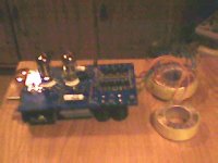
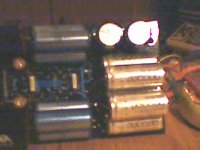
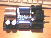
Good preamp. But remove the electrochemical condenser, bypassing the cathode of the 2nd stage. Power supply of heaters must be DC, stabilized.
Regards, P.Lacombe.
Regards, P.Lacombe.
Topology seems to be OK. At the expense of incurring your wrath, I have to say that it is not my cup of tea.
I guess, the purpose of this preamp is for use in a band and when the band is not playing you would like to play CD or radio through your stage amp. Am I correct?
Why do you need to raise the cathode voltage on the input tube? I am referring to the 47K resistor. If you remove this resistor, then you may not need the 10nF input capacitor. I do not prefer cathode followers in general unless you want to run long cables from the preamp.
Mohan
oh.. I woulndt know its not my design it is called REMUS and was phublished in Audio Video (a swedish mag in early 90:s)
and the circuit is rumored to sound really good (and meassure well for a tube circuit)
/micke
and the circuit is rumored to sound really good (and meassure well for a tube circuit)
/micke
Micke,
I agree with both of the previous posts:
--Drop the cathode follower at the input. There are a number of reasons to use a follower, but for the life of me I can't think of one to justify the use of one as an input buffer. One at the output is fine. (Incidentally, I'd consider raising the 100k at the output to 1M--it's there to drain DC off the back end of the coupling cap at turn-on, which is fine, but it will also be in parallel with the Zin of the amp/crossover and constitutes an unnecessary load.)
--Omit the cap for the cathode. The gain will drop when you do so, but you'll not only avoid an electrolytic, you'll pick up a bit of local degeneration (aka feedback) which will reduce distortion. These days, you don't really need a lot of gain in a preamp.
Grey
hifi said:
does anybody here have any info on the russian triode 6cc41 ??
/micke
I guess you meant 6c41c ?
Here is couple of links I have bookmarked.
http://www.mclink.it/com/audiomatica/tubes/6c41.htm
http://www.tubes.ru/techinfo/GlassTubes/6s41s.html
Argo
6cc41
Hello,
why don´t you ask the seller, Gintaras Sakemas is always helpful. Think he can scan the original data sheet for you.
Good Luck,
Regards from germany,
Reinhard
Ad on: Look at www.tubes.ru, glass tubes and then
6N2P. You find the 6CC41. Looks very similar to a 12AX7. Little higher transconductance and internal shield at pin 9.
Reinhard
Apparently it's a near ECC83 equivalent.
Use TDSL for all your tube data questions..
http://www.duncanamps.co.uk/cgi-bin/tdsl3.exe/searchform
Use TDSL for all your tube data questions..
http://www.duncanamps.co.uk/cgi-bin/tdsl3.exe/searchform
Do you think it is usable in the circuit above it calls for half an ecc82 and half a ecc83 ?...
/micke
/micke
Thanks Grey for clarifying what I wanted to say. Sometimes, I think ahead of myself and miss the essence of what I need to say. I am still a one finger typist and my brain runs away….
By the way, how do I post a schematic and what types of file can be pasted?
Mohan
By the way, how do I post a schematic and what types of file can be pasted?
Mohan
Sounds like you are looking for a 7247....but if you are working stereo on one chassis use a ECC82 and ECC83 combo and a bit more wire. The 7247s are getting a bit pricey.
Take that back....for stereo you need 1 ECC83 (1/2 per side) and 2 ECC82s (1 per side). The 7247 is 1/2 each. For a nice SE EL84 stereo amp design check out the Eico AF-4. I am building this with 1 12AX7 and 1 12AU7 instead of 2 7247s, leaving the tone controls out and adding a choke and larger caps in the power supply. Note that the signal goes through the 12AU7 side if the tube first. The copy I have of this is too large to post here.
- Status
- Not open for further replies.
- Home
- Amplifiers
- Tubes / Valves
- what do you tube gurus think about this?


