Marcel,
Verilog is meant to be a hardware descriptor language, thus you have to think about defining hardware and not think like software code. Defining constants should be approached by thinking what sort of hardware they would be - ROM, RAM, registers, tie high/low? Making a 32-bit constant means it might be advantageous to define a ROM section of some sort, or use flash storage if the FPGA supports it.
I agree the testbench side of things can become a bit clunky, but it's tolerable.
SystemVerilog largely simplifies the reg/wire issues of original Verilog with the "logic" data type, as well as the "always_comb", and "always_ff" blocks. Structural code cleanliness with regards to combinational and sequential logic is paramount to avoid unintentional latches in hardware.
There's nothing better (at the moment) for hardware descriptor code, and honestly what can be done with it is quite impressive - your latest ARM-powered device is all SystemVerilog.
How about VHDL?
When I started to play with FPGAs for my valve DAC project, I had the choice between using Verilog (plain old Verilog) and VHDL. Not having any experience with either language, I chose Verilog and regretted it ever since. Of course I did learn to work around the stupidest features (I can't call them bugs because they are apparently defined like that in the Verilog standard).
When I started to play with FPGAs for my valve DAC project, I had the choice between using Verilog (plain old Verilog) and VHDL. Not having any experience with either language, I chose Verilog and regretted it ever since. Of course I did learn to work around the stupidest features (I can't call them bugs because they are apparently defined like that in the Verilog standard).
Could we conclude that the difference between NOS and OS (with reconstruction filter) is due to the poor implementation of the reconstruction filter? And oversampling in itself does not have any subjective perfomance impact?
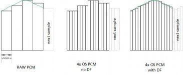
According to the attached example (in the middle), the analog output of a 4x OS should be essentially the same as the original NOS signal. Or the aliasing images are shifted up around 4x the sampling frequency? How is it possible if both NOS and 4xOS gives the same analog signal?
(the interval in the first example is 1/44100 s)
Attachments
Last edited:
Could we conclude that the difference between NOS and OS (with reconstruction filter) is due to the poor implementation of the reconstruction filter?
I would agree. But also mention that it heavily depends on the type of filter (Mostly FIR is used)
Also like to bring back to mind the experiment I did with HQplayer...
With FIR not so good, but better than poor FIR filters (like in Roon or in hardware)
With the Polynominal-1 filter almost NOS sound with small extra: Voices and alike a re a tad smoother
I would say, all those things add up to the conclusion and are confirming each other.
.
Could we conclude that the difference between NOS and OS (with reconstruction filter) is due to the poor implementation of the reconstruction filter? And oversampling in itself does not have any subjective perfomance impact?
We did not determine the exact mechanism behind what causes typical-OS interpolation-filters to introduce audible artifacts. There are several possibilities. It may not be accurate to simply say that it is due to implementation.
According to the attached example (in the middle), the analog output of a 4x OS should be essentially the same as the original NOS signal. Or the aliasing images are shifted up around 4x the sampling frequency?
Perfect SINC-function based interpolation results in perfect reconstruction of the original signal. However, there is no such thing as perfect SINC-function interpolation in practice. All practical digital FIR filter based solutions are inherently compromised in some respect or another.
The image shifting almost works that way. The image-bands manifest in mirror-imaged pairs, folded around integer multiples of the output conversion rate. So, for 4xOS of a 44.1kHz base sample rate, and with a 22kHz signal band:
The first mirror-folded pair are centered at 1 x 176.4kHz = 176.4kHz.
So, 176.4kHz - 22kHz, and at 176.4kHz + 22kHz. Giving a lower image-band spanning from 176.4kHz down to 154.4kHz, and an upper image-band spanning from 176.4kHz up to 198.4kHz.
The next mirror-folded pair are centered at 2 x 176.4kHz = 352.8kHz.
So, 352.8kHz -22kHz, and at 352.8kHz + 22kHz. Giving a lower image-band spanning from 352.8kHz down to 330.8kHz, and an upper image-band spanning from 352.8kHz up to 374.8kHz.
This pattern continuously repeats, progressing higher in frequency.
How is it possible if both NOS and 4xOS gives the same analog signal? (the interval in the first example is 1/44100 s)
Ignoring the fundamental difference in treble droop of NOS for the moment. OS relocates the image-bands higher in frequency. That is really all that it does. It's greatest advantage over analog reconstruction filters is that digital FIR interpolation-filters are able to fully suppress the first image-band, while leaving an adjacent signal band untouched.
For CD rate sampling, the first image-band can drop as low as; 44.1kHz - 22.05kHz = 22.05kHz. Which is right up against the signal band. Only a digital OS filter is capable of cleanly separating the two.
Oversampling does not per se remove image bands, it's the digital filter usually involved in the oversampling process.
If 4x "oversampling" produces 4x the same sample in a row (as shown in #1784) there's clearly no digital filter involved and the image bands will be exactly the same as without oversampling.
If 4x "oversampling" produces 4x the same sample in a row (as shown in #1784) there's clearly no digital filter involved and the image bands will be exactly the same as without oversampling.
OS relocates the image-bands higher in frequency.
If 4x "oversampling" produces 4x the same sample in a row (as shown in #1784) there's clearly no digital filter involved and the image bands will be exactly the same as without oversampling.
Now I am bit confused... I am talking about OS without digital filter.
Except that our hearing is not obstructed by a presence of images.Ignoring the fundamental difference in treble droop of NOS for the moment. OS relocates the image-bands higher in frequency. That is really all that it does. It's greatest advantage over analog reconstruction filters is that digital FIR interpolation-filters are able to fully suppress the first image-band, while leaving an adjacent signal band untouched.
And a fundamental NOS drop is attributed to the sample/hold operation, it will be the same when sample/hold is applied to the oversampling.
From our perspective NOS drop is not perceived in practice, unless images are filtered out. It indicate that our hearing do not interprete analog waveforms, but it is something based on a sensors pulse response (that benefits from images).
Now I am bit confused... I am talking about OS without digital filter.
There is no such thing as OS without a digital filter.
Re-reading post #1784, the center diagram in the image depicts a ZOH DAC outputting the exact same sample four times in succession, except each sample is 1/4 the base sample period. That, then, results in the same DAC output as in the first diagram on the left, should no other operations be performed. What it does do, however, is make it possible to open 4x as much output spectrum as before. Which is only realized, should the current samples be passed through a digital low-pass filter. Which relocates the original image-bands in to the increased spectrum which it opens.
Last edited:
OK, I mean upsampling by an integer coefficient (2x or 4x or even 8x).
I’m confused by that response. Try restating exactly what it is you are trying to find out.
Hi all,
I am in a busy time of life (will be moving home shortly) and thus I have been reading this thread only on and off - but nevertheless so with great interest when time allowed. The topic of the thread and the - would it be ok to say quite scientific? - approach to it has been very informative and a fine learning process.
On a more personal level I have also enjoyed the overall positive tone of voice in the thread. Whereas in some other threads I tend to be a bit hesitative as to whether I would like to open the thread and read the latest posts, even if the subject is interesting to me - I have just read into this thread for the curiosity & pleasure of hearing about the findings & exchange of views etc. A sincere Kudos to Ken & others for - as I have observed & interpreted this - stearing the conversation and exchange in this direction 😉
That said I would like to add just one comment in relation to conducting comparative tests at different sampling frequencies.
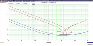
In my experience D/A converters rarely perform identically at different sampling frequencies. As I have seen it they typically have a higher (and "slightly" altered) distortion/noise level and spectrum at higher sampling frequencies. I guess the root causes of this may be many - but one obvious one is the change of impedances of the decoupling capacitors relative to frequency. I suppose you may already know about this but e.g. in the attached screendump the ubiquitous 100 nF decoupling capacitor has an impedance of ~8 mohms at ~12 MHz whereas the impedance is ~140 mohms at 22.5 MHz.
Assuming that a D/A converter has "a good deal" of noise to be decoupled around the sampling frequency (as I have noticed is the case with e.g. the PCM1794), then going from e.g. 192 kHz sampling to 384 kHz sampling may cause some changes in the PSU decoupling efficiency - just for this reason.
I realize that part of the basis of your investigations has been to change the sampling frequencies - yet at this point in time I personally am a bit wary of comparing sound impressions across sampling frequencies due to this change of performance.
I realize that this is a slight digression but nevertheless hope that it may appear relevant.
Cheers & thanks again for an intriguing thread 😉
Jesper
I am in a busy time of life (will be moving home shortly) and thus I have been reading this thread only on and off - but nevertheless so with great interest when time allowed. The topic of the thread and the - would it be ok to say quite scientific? - approach to it has been very informative and a fine learning process.
On a more personal level I have also enjoyed the overall positive tone of voice in the thread. Whereas in some other threads I tend to be a bit hesitative as to whether I would like to open the thread and read the latest posts, even if the subject is interesting to me - I have just read into this thread for the curiosity & pleasure of hearing about the findings & exchange of views etc. A sincere Kudos to Ken & others for - as I have observed & interpreted this - stearing the conversation and exchange in this direction 😉
That said I would like to add just one comment in relation to conducting comparative tests at different sampling frequencies.
In my experience D/A converters rarely perform identically at different sampling frequencies. As I have seen it they typically have a higher (and "slightly" altered) distortion/noise level and spectrum at higher sampling frequencies. I guess the root causes of this may be many - but one obvious one is the change of impedances of the decoupling capacitors relative to frequency. I suppose you may already know about this but e.g. in the attached screendump the ubiquitous 100 nF decoupling capacitor has an impedance of ~8 mohms at ~12 MHz whereas the impedance is ~140 mohms at 22.5 MHz.
Assuming that a D/A converter has "a good deal" of noise to be decoupled around the sampling frequency (as I have noticed is the case with e.g. the PCM1794), then going from e.g. 192 kHz sampling to 384 kHz sampling may cause some changes in the PSU decoupling efficiency - just for this reason.
I realize that part of the basis of your investigations has been to change the sampling frequencies - yet at this point in time I personally am a bit wary of comparing sound impressions across sampling frequencies due to this change of performance.
I realize that this is a slight digression but nevertheless hope that it may appear relevant.
Cheers & thanks again for an intriguing thread 😉
Jesper
Attachments
With that thinking, I expect that you'd be concerned about what happens inside the laptop / PC when you force the CPU to run at higher frequencies AND voltage levels when you upsample... like with HQPlayer and the CPU insanely intensive DSD modulators. Maybe another reason just to stream the native files, bit-perfect, and refrain from upsampling...??
Hi all,
...On a more personal level I have also enjoyed the overall positive tone of voice in the thread. Whereas in some other threads I tend to be a bit hesitative as to whether I would like to open the thread and read the latest posts, even if the subject is interesting to me - I have just read into this thread for the curiosity & pleasure of hearing about the findings & exchange of views etc. A sincere Kudos to Ken & others for - as I have observed & interpreted this - stearing the conversation and exchange in this direction 😉
That said I would like to add just one comment in relation to conducting comparative tests at different sampling frequencies...I realize that part of the basis of your investigations has been to change the sampling frequencies - yet at this point in time I personally am a bit wary of comparing sound impressions across sampling frequencies due to this change of performance.
I realize that this is a slight digression but nevertheless hope that it may appear relevant.
Cheers & thanks again for an intriguing thread 😉
Jesper
Hi, Jesper,
Thank you, for those kind words.
I agree, the many variables of conducting a proper, scientifically controlled experiment make it extremely difficult to realize confident conclusions utilizing only DIY hobbyists and resources. Ultimately, however, unless one is a pure objectivist, scientifically 'proven' conclusions don't dictate system decisions anyhow. Subjective evaluation will play some role in either making or confirming audio system building decisions. What I hope our thread has accomplished is to encourage readers to consider system building approaches which they otherwise may not have, via their own personal subjective evaluation.
Last edited:
There is no such thing as OS without a digital filter.
Pleas correct me somebody if I'm wrong, but technically repeating a sample twice to achieve 2x FS actually is oversampling. As is using one original sample and one zero sample (zero stuffing). This will of course not get rid of image bands...
Pleas correct me somebody if I'm wrong, but technically repeating a sample twice to achieve 2x FS actually is oversampling. As is using one original sample and one zero sample (zero stuffing). This will of course not get rid of image bands...
See my clarification in post #1792, above: https://www.diyaudio.com/forums/digital-line-level/371931-makes-nos-sound-180.html#post6778824
Part of the issue is that in the DSP world, this is more considered multi-rate processing, not oversampling. My view is that oversampling more correctly applies to ADC processing, not to DACs. However, the OS terminology has taken hold in the digital audio industry, where it always refers to rate conversion by digital interpolation-filter. I suppose, this is largely just semantics.
- Home
- Source & Line
- Digital Line Level
- What do you think makes NOS sound different?