Thx Scott,Hans I've said this before, LTSpice is a nice tool and service to the DIY community but it is not a general purpose research tool. The fully vetted IEEE math library is available for free in any number of tools. You have available more statistical functions (random number generators, etc.) than you could ever use all fully described and used by almost all scientific organizations, CERN, LIGO, etc.
Yes I know and LTSpice is indeed a nice and easy tool to get some insight in what's going on, but it's never a scientific proof.
Sometimes it's very effective with Noise analysis in analogue circuitry, but a transient analysis with simplified models and sources is mostly a relatively coarse approach of what really happens.
Hans
Roderick, this whole discussion about Gaussian/normally distributed noise started because of the peculiarities of Hans's simulator. It produces noise with an unspecified distribution with values that are guaranteed to be in between -0.5 and 0.5, and then we started guessing what the distribution might be.
In general, it indeed makes more sense to use sums of rectangularly distributed random numbers for dithering.
In general, it indeed makes more sense to use sums of rectangularly distributed random numbers for dithering.
You have demonstrated that unmodulated noise from both DACs doesn't guarantee that the difference is unmodulated - as the noise is not independent, noise from one DAC can cancel noise from the other DAC. In my scheme they complement rather than cancel each other: in each 1/2 LSB interval, one produces noise while the other doesn't. The total noise is periodic as a function of the input signal with a period of 1/2 LSB, which is solved by randomizing over 1/2 LSB with the differential dither.
Hi Marcel,
Your explanation sounds to me a bit as a "proof by contradiction". 😀 😀
Knowing that LTSpice is not perfect and that {White} is not exactly uniform, that's why I have used {1.13*White} from the beginning to get the same 0.288 rms value as an RPDF.
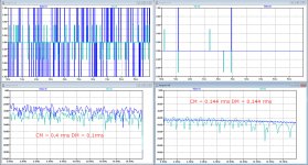
So, to get some feeling of what your proposal would bring despite the above restrictions, I took in one case what I used before: TPDF CM noise of 0.4 LSB rms and RPDF DM noise of 0.1 LSB rms. All three noise sources uncorrelated.
The second case was CM and DM both 0.144 LSB rms RPDF and both uncorrelated.
See image below to illustrate what happens when offering a DC signal.
From the corrupted Dac signal of the second case at the right, the diff amp could not repair what was intended to get as in case 1 at the left.
Hans
.
Attachments
The common-mode dither in my calculation has an expected value of 1/4 LSB. Does adding 1/4 LSB of DC to your common-mode dither help?
If not, I'll see if I can get it to work in Free Pascal.
If not, I'll see if I can get it to work in Free Pascal.
Last edited:
The common-mode dither in my calculation has an expected value of 1/4 LSB. Does adding 1/4 LSB of DC to your common-mode dither help?
If not, I'll see if I can get it to work in Free Pascal.
Do I have to shift the DM noise also ?
Hans
P.S. With the 0.25 LSB shift, it's quite a lot better, almost the same as with 0.4 rms Tri.
Last edited:
FYI-
The concluding investigation report is progressing well. I expect to publish it by this Sunday.
The concluding investigation report is progressing well. I expect to publish it by this Sunday.
Do I have to shift the DM noise also ?
Hans
P.S. With the 0.25 LSB shift, it's quite a lot better, almost the same as with 0.4 rms Tri.
No, just the common mode dither.
The idea is to shift the points where the two quantizers switch as a function of the input signal in opposite directions, so they work staggered.
o.k., I’ll show you the result later this afternoon.
Compared to the other sim with DM band noise around 10Khz, the spectrum is slightly raised below 1Kz, but that may be a LTSpice artefact.
Hans
Compared to the other sim with DM band noise around 10Khz, the spectrum is slightly raised below 1Kz, but that may be a LTSpice artefact.
Hans
Regarding the 176.4 Experiment
I’ve before posted the below thoughts regarding the 176.4 experiment:
It makes sense that some of us heard a greater difference between 44.1 and 88.2, than between 88.2 and 176.4. Because, the ZOH based 20kHz droop is approximately -3.17dB at an 44.1 rate, -0.75dB at an 88.2 rate, and -0.2dB at an 176.4dB rate. Therefore, the incremental difference between 44.1 and 88.2 is 2.42dB, while between 88.2 and 176.4 it is 0.55dB. A much smaller incremental change.
As I’ve also before mentioned, and aside from the above difference in treble droop, one simply doesn’t expect there to be a subjective difference between 88.2 and 176.4 as, in either case, the image-band residual spectra are moved well up into the ultrasonic. I speculate that any actual subjective difference is rather due to differences in dither, or, perhaps, more likely, the available spectrum over which the dither can be spread.
My thoughts about the tabulated scoring results:
First, I include the usual results disclaimer. Our testing sample size simply is far too small to place statistical confidence in the result indications. That aside, the average score of those who utilized an OS DAC, is +0.42, possibly indicating a slight preference for 176.4 upsampling, over 88.2. Remember, the scoring range is -2 to +2, with 0 indicating no preference for one upsampling rate over the other. The average score of those utilizing a NOS DAC, however, is +0.78, indicating a still relatively small but, a little less random preference.
If I find anything interesting about those results, it’s that the average score of those utilizing an NOS DAC preferred 176.4 by a score nearly double that of those who utilized an OS DAC. It’s impossible to draw any conclusions from that. A possibility may be a non-transparently performed interpolation by the OS DACs. However, that’s only speculation. One other interesting result is that there were no responses where 88.2 was preferred over 176.4. I suppose, that may be due to a couple of psychological factors. Among which, could be the assumption that the 176.4 must be superior, I don’t know.
Last edited:
Marcel,
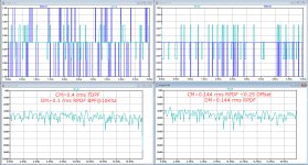
Here you are with the LTSpice results for your proposed noise setting.
DM 0.144 rms RPDF+0,25 offset and DM 0.144 rms RPDF.
As you can see it works, although showing a slightly raised spectrum below 10Khz for DC input.
As mentioned I have used 10Khz 0.1rms BPF RPDF DM noise.
Question is, although mathematically correct, why sitting on the very edge of what's still possible, while this topology is completely insensitive to the CM noise level.
Even 2.0 rms CM noise still gives the same output spectrum, so there's no need at all in trying to be economical.
Hans
.
Attachments
I haven't a clue how much impact it has, but the filtering will change the probability distribution to some extent.
To me the possibility to stagger the quantizers and get away with half dither is useful for the differential dither and only an interesting peculiarity for common mode dither. I think it's better to use a large even multiple of the minimum common mode dither to randomize errors due to DAC differential non-linearity. How far you can go with this will depend on gain errors, among other things.
To me the possibility to stagger the quantizers and get away with half dither is useful for the differential dither and only an interesting peculiarity for common mode dither. I think it's better to use a large even multiple of the minimum common mode dither to randomize errors due to DAC differential non-linearity. How far you can go with this will depend on gain errors, among other things.
I hope we have reverse engineered it sufficiently to answer Ken's questions.
Reverse engineered it, hell, you guys improved it!

It maybe would be helpful to all us non dither technique experts, to show a simplified conceptual diagram of what the final solution vision is. Perhaps, something like the simplified diagram shown at the top of page 14 in Anagram’s data sheet. 😀
I'd like to chime in here. I admire the work that's been put in this so far.
If anybody is interested I'd like to take this one step further with freely available math/statistics tools, namely numpy/scipy and come up with a public repo with DAC/noise shaping/modulator/DEM simulation examples.
I will gladly take the role of the maintainer, but I will need the input of math/sim experts along the way. I don't want to clutter this thread, that's why I kept silent up to now. All your work (respective people will know I mean them) is amazing to me.
Time to split this off to a new thread?!
Reverse engineered it, hell, you guys improved it!
It maybe would be helpful to all us non dither technique experts, to show a simplified conceptual diagram of what the final solution vision is. Perhaps, something like the simplified diagram shown at the top of page 14 in Anagram’s data sheet. 😀
Can you live with this diagram ?
Hans
.
Attachments

Can you live with this diagram ?
Hans
.
That's perfect, Hans.
Exactly what I was hoping for.
Thanks
Can you live with this diagram ?
Hans
.
What function are the quantizer blocks, located in between the adder and the DAC blocks, performing? I normally associate quantizers as being inside the DAC unit, which these aren't.
Last edited:
When doing the FIR filter computations, a much longer word length is used to avoid excessive noise addition.
PGGB is using 64 bit, but it could also be 32 bit.
The same applies to the noise generators, they will have to produce much longer word lengths.
When going to the D/A converter, the used extra long word length has to be reduced to 24bit for most Dac's.
This step is what happens in the quantizer, rounding and truncation.
Hans

- Home
- Source & Line
- Digital Line Level
- What do you think makes NOS sound different?