I guess we will have to agree to disagree. Otherwise, nothing I have ever built is worth anything in your book. I suppose PSRR and CMRR are just meaningless numbers when it comes to audio.
Jocko
Jocko
LTP with curr. mirror or resistor
Hello all!
Regarding the LTP with resistor or current mirror:
When using a current mirror the simulation shows that the offset voltage at the output is 9.5mV with some 0.5mV oscillation at the output (approx. 12.5 kHz). Don't know from where this comes, but I will find out...
When I use a resistor in the collector of T1 (no curr. mirror), 1k9 is about right, giving almost no oscillation and an offset voltage of 176mV at the output.
Using 1k8 gives -150mV and 0.5mV oscillation at the output.
Can somebody explain me that this "small" change in resistance gives so different results.
I mean the change is a bit over 5%.
In real life the components together are more than 5% different...
Or am I on the wrong way?
Thanks,
Patrick
Don't believe the distortion numbers your simulation program gives. They tend not to be accurate.
Using a current mirror in the LTP may give you more open-loop gain than you want or need.
Jocko
Using a current mirror in the LTP may give you more open-loop gain than you want or need.
Jocko
Hello Patrick
Nothing wrong, it's all right.
The change in the value of the resistor is 5.5%.
The change in the output voltage is : 0.150 + 0.176 / 60 = 0.54%
In a final prototype, an adjustable resistor must be placed somewhere, to cancel offset voltage. But it's an evidence that in mass production, an adjustable resistor and the adjustement are more, more expansive than a current mirror...
Regards, P.Lacombe.
Jocko
If you design an electrocardiograph, the most important is CMRR and PSRR, but 1 % linearity is suffiscient.
Things are totally different if you are designing high quality audio amplifiers. The most important is sound quality, 0.1% linearity may be sufficient or no, depending of the kind of non-linearity. CMRR and PSRR are not so important (well known high quality amplifiers have ridiculous PSRR, 12 dB or so).
When you design an audio amplifier, never forget that it must be above all, first of all, a musical instrument.
Regards, P.Lacombe.
Measurements
There is no reason that a good sounding amp should have to measure bad. PSRR is important to how an amp or preamp sounds. If not, why does attention to good power supply design pay such large sonic dividends to an amplifier design? A circuit's interaction with its power supply is one the most important factors in amplifier design.
H.H.
I never said linearity is not important. I have stated numerous times that this is perhaps the most important criteria in designing audio electronics. But to say that a "resistor will always have lower distortion" is not quite right. There are some places a resistor by itself will not work properly. A current source needs to be high impedance, and a resistor by itself will not cut it. You cannot, even though some try, hook a resistor to the output of a R-2R ladder DAC and expect the linearity the part is capable of.
Had you stated that a current mirror is not always a good choice, then we would not have a disagreement. I would not use one in a LTP simply because the gain will be to high, regardless of linearity.
Yes, there are "well-known" amps with poor PSRR. But you previously metioned the term "maximum sound clarity". While many like the sound of thses amps, I really don't believe anyone would say that they have "maximum sound clarity".
Jocko
HarryHaller,
I agree with you. Just, we are not speaking about same things...
Jocko,
I say that a resistor will work better than a current mirror in the case we are examining, in this particular design. Of course, I don't use simple resistor in R 2R ladder !
Regards, P.Lacombe.
I agree with you. Just, we are not speaking about same things...
Jocko,
I say that a resistor will work better than a current mirror in the case we are examining, in this particular design. Of course, I don't use simple resistor in R 2R ladder !
Regards, P.Lacombe.
swede said:pprasse: What software do you use for your schematics?
//magnus
The first schematics are drawn in eagle (www.cadsoftusa.com).
The schematic I use for simulation is drawn with gschem which is for linux only (yet).
The spice netlist is made using gnetlist.
And I use gwave to view the simulation output.
gnetlist, spice and gwave are packed in a small shellscript to speed up the process of simulation.
Patrick
Final schematic
Hello all!
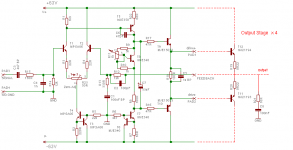
Here is the final schematic of my amplifier.
I did not use a current mirror in the LTP as it works similarly well with one resistor.
It just took me some time to find out the right value.
Some other components values have changed too.
The DC offset without the pot (R23, only R3, R4 = 47R ) is way under 100mV.
I'm looking forward to building it.
But before doing this I'll go on holiday on friday. 🙂 🙂 😀
Everyone's invited to post comments about the schematic!
Regards,
Patrick
Hello all!
Here is the final schematic of my amplifier.
I did not use a current mirror in the LTP as it works similarly well with one resistor.
It just took me some time to find out the right value.
Some other components values have changed too.
The DC offset without the pot (R23, only R3, R4 = 47R ) is way under 100mV.
I'm looking forward to building it.
But before doing this I'll go on holiday on friday. 🙂 🙂 😀
Everyone's invited to post comments about the schematic!
Regards,
Patrick
Attachments
bypass C1,C3,C5 and C7 with some 100nF filmcap. You could always remove them when you do not think they are neccesary.
Also add a small series resistor to the power BJT's to prevent oscillation ... Looks like they are not mounted on the same board!? Those resistors could always be replaced with jumps if they are not neccesary.
But i would like to hear what the result is ... bandwidth .. offset .. etc.
Sonny
Also add a small series resistor to the power BJT's to prevent oscillation ... Looks like they are not mounted on the same board!? Those resistors could always be replaced with jumps if they are not neccesary.
But i would like to hear what the result is ... bandwidth .. offset .. etc.
Sonny
The output stage transistors are mounted directly on the heatsink on another PCB.
What's the advantage of bypassing the caps with film types?
The simulation says that the -3dB freqs are 11Hz and 65kHz.
The offset voltage without load and input is -11mV.
The offset at 1V input / 8R load is 92mV.
I post the real results as soon as I have built a prototype.
Patrick
What's the advantage of bypassing the caps with film types?
The simulation says that the -3dB freqs are 11Hz and 65kHz.
The offset voltage without load and input is -11mV.
The offset at 1V input / 8R load is 92mV.
I post the real results as soon as I have built a prototype.
Patrick
pprasse said:
What's the advantage of bypassing the caps with film types?
Patrick
To get better highfrequency performance of the amp. More clear sound.
Sonny
Everyone's invited to post comments about the schematic!
You shouldn't have said that. When do we start nitpicking on your transistor choices? I'll let sonnya do that, as he has a better idea of what is available where you are than us rude Yanks. (Actually, us Texans don't answer to "yank", but for brevity sake.........) [joke]
Jocko
Can make it even better?, in my idea, this was the best forum thread.
I think this cooperation made amplifier, was a great moment of our forum.
But a good time already passed, and now, i am asking if this schematic is really finished.
What about stop resistors at the output base?
It looks very good, can make it even better?
regards,
Carlos
I think this cooperation made amplifier, was a great moment of our forum.
But a good time already passed, and now, i am asking if this schematic is really finished.
What about stop resistors at the output base?
It looks very good, can make it even better?
regards,
Carlos
Pierre Lacombe is an old and hard experienced Enginneer and famous ham too
Since i was young i was reading his texts in Ham Magazines.
This way, i understand that he did not left nothing to finish.
My respects to Doctor Pierre Lacombe.
regards,
Carlos
Since i was young i was reading his texts in Ham Magazines.
This way, i understand that he did not left nothing to finish.
My respects to Doctor Pierre Lacombe.
regards,
Carlos
- Status
- Not open for further replies.
- Home
- Amplifiers
- Solid State
- What do you think about this amp schematic?