Cortez said:> So a large cross sectional area with a flat shape is the best ?
Flat cables are better in high freqs based on skin effect ?
Directly through the rails or through the circuit ?
So the point is to have a GND wire with the minimum resistance as possible ?
So a low impedance would be the best at high frequency, cause these noise are mainly at high freqs.
Hmm, maybe a good and small cap could be used somehow as a high freq grounding ?
>>>I'm not sure of what point I'm supposed to be answering here. I feel like I've described why I believe this works and conceptually how to implement it.
My experience is a wire doesn't work and if you put in a hundred bypass caps to shunt noise around a circuit and it's routed back
to the the main ground/circuit reference through 8 inches of wire (any gauge) above some frequency they are not going to work. Mixing any of this noise with the return currents from the circuit has an effect on the low level detail. I've experimented with this and refined my understanding of this and other layout aspects over many years. All of these concepts are well documented in the PCB layout and instrumentation technology.
The original post asked for layout advice so I thought I'd throw it out there, since I hadn't read anything similar on the site over the past couple of months. I guess my thought was that a DIYer would try it and some discussion would in-sue.
My addition to simulation and theory is, building and listening.
Regards, Mike.
😕AndrewT said:Hi,
don't get your Xs mixed up with your Ys
Yrated from line to earth.
MikeBettinger said:
I'm not sure of what point I'm supposed to be answering here.
Ok sorry, I wasnt clear: I wont have a metal chassis in my amp,
but I would try this, so how can I imitate a chassis to achieve a
good grounding at every freq like a metal chassis does ?
The flat shape is the point, or that it surrounds the circuit ?
EJ said:
are you sure about the direction of stray magnetic field direction?
according the Ampere's Law (know as the right hand rule), I don't see why the field direction is straight up through the center of toroid.
Well I thought I was, but I could be wrong? I'm familiar with the right hand rule as it applies to the 2 axis magnetic field within the toroid core but this is the Z axis, wasn't that one of the reasons why even with encased, shielded toroids they're still always horizontally mounted if anything remotely close is sensitive? It wouldn't have been hard for anyone to just use an L-bracket to mount 'em 90' rotated if it weren't the case.
Cortez said:
😕
Ok sorry, I wasnt clear: I wont have a metal chassis in my amp,
but I would try this, so how can I imitate a chassis to achieve a
good grounding at every freq like a metal chassis does ?
The flat shape is the point, or that it surrounds the circuit ?
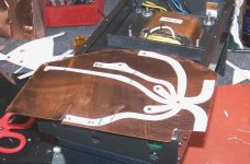
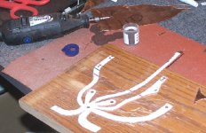
Actually what I use these days, but in an attempt to keep the concept simple didn't suggest, is copper sheeting cut to shape with a 409 cutting blade and a dremel. I'll see if I have a picture to attach. I make a template from thin cardboard to interconnect my various ground points then transfer it to the copper sheet.
I normally use .5mm thick copper and produce traces approximately 10mm wide for signal and supply returns and approximately 13mm for speaker return. It's all done freehand so it varies. I calculated it once and, if my memory serves me, the 13mm is approximately equivelent to an 8 gauge round wire.
I'll send a picture when I get home.
Mike.
Actually the sheet copper is approximately 1mm thick, the conversion from inches in my head didn't process properly.
Mike.
Mike.
Hi,
a bit thicker than 4oz cladding on a PCB then.
That makes 5 grades of thickness I need to remember;- zero, 1oz, 2oz, 4oz and a bit thicker!😉
a bit thicker than 4oz cladding on a PCB then.
That makes 5 grades of thickness I need to remember;- zero, 1oz, 2oz, 4oz and a bit thicker!😉
Cortez said:Originally posted by AndrewT
Hi,
don't get your Xs mixed up with your Ys
Yrated from line to earth.
😕
http://www.justradios.com/Y2capacitors.html
http://www.justradios.com/safetytips.html
Mike, thx, I would be grateful for a picture.
Otherwise where the different gnd points are meeting then ?
Do you have a picture about the layout with these copper sheets ?
Otherwise where the different gnd points are meeting then ?
Do you have a picture about the layout with these copper sheets ?
Thanks Cp,
that safety tips link was rather well written.
http://www.justradios.com/safetytips.html
Just to expand on his X means "aCROSS" the lines.
The Y can be seen as connecting both lines down to the ground.
that safety tips link was rather well written.
http://www.justradios.com/safetytips.html
Just to expand on his X means "aCROSS" the lines.
The Y can be seen as connecting both lines down to the ground.
Good grief Mike what are you starting here ?
I must have read a hundred times, on this forum and other DIY sites, discriptions of grounding schemes all of which would suggest that yours is totally tabboo.
Normaly some kind of star topology is described to keep ground currents out of the signal path. To solve the issue of ground currents between units it is insisted that the amps signal/power ground is never conected to the chassis and mains safety ground, including the input output jacks.
Now I could somehow go along with these recomendations apart from the safety ground part. You see if the input/output jacks don't have their shields grounded to safety ground then in some rare and weird fault condition they could go to live mains with dire consequences. This seems unlikely but I've noticed in my life that rare and weird things happen all the time.
You are presenting the first grounding scheme that makes me happy with the safety issues.
As it happens I have a tube/MOSFET hybrid amp built on a wooden chassis that suffers from a little hum. Built according to the usual recipie. Looks like it will get a ground plane and reconnect as you suggest and hear what happens.
I look forward to you pictures.
heater said:Good grief Mike what are you starting here ?
Actually I'm just looking for a bit of feedback and discussion.
First, there is no reason (sonically) you cannot use a safety ground. But, if you go back 25 years very few audio components used a three wire power cord, most designers relied on the power transformer for isolation from the AC mains. But that's just an observation not a suggestion. From my perspective the saftey ground can go to the preamp and the rest of a single ended system can rely on it to provide a that functionality. This is a whole other discussion on minimizing leakage currents between components and proper grounding.
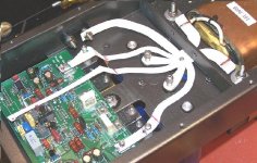
Second, as you can see in the pictures I am using a star type ground but I'm using it to control return currents from functional circuit blocks, etc. not every stage.
I notice that both you and Cortez are not using metal chassis'. Is this a current approach? I've recently tripped across this and other forums. Obviously there is a very active group of audio experimenters. It's good to see this. I've been doing my own thing for my own amusement over the years.
The simple suggestion in my first post will improve any good design. The pictures show a extended version that works with my designs, I'm not sure how it will work with what I call capacitor farms or poor circuit layouts (circuits requiring complicated compensation) . No reason it should not, but experimenting should only be done by the strong of heart.
Enjoy, Mike.
Attachments
Hi Mike !
I guess your design has 2 specialites, so lets separate them:
1) Using flat cables, improves high frequency behaviour based on the skin effect.
Well, that sounds true, cause we have a much greater area to conduct at high freqs.
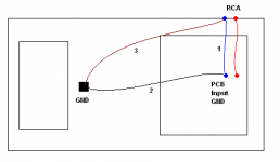
2) grounding the input directly from the RCA to the main GND
I attach a picture to ease the explanations.
Now lets forget the a cables have limits in freq, resistance, etc,
lets pretend they are ideal, so we can concentrate on their funcionality.
There is 3 GND points on this model:
- RCA GND
- Main GND (trafo, filter caps...)
- PCB Input GND
Based on this figure we could get all of the possible combinations.
So I think the conventional layout, what Mike wanted to improve
is when there are only the wires #1 and #2, because then noise
currents would create voltage on the resistance of wire #2.
And what Mike is using: #3 to route everything, noise and interference
from the interconnect cable's ground wire to our main GND reference
point with a low impedance path, and to the PCB we are using wire #1 (wire #2 isnt there).
Am I right ?
I guess your design has 2 specialites, so lets separate them:
1) Using flat cables, improves high frequency behaviour based on the skin effect.
Well, that sounds true, cause we have a much greater area to conduct at high freqs.
2) grounding the input directly from the RCA to the main GND
I attach a picture to ease the explanations.
Now lets forget the a cables have limits in freq, resistance, etc,
lets pretend they are ideal, so we can concentrate on their funcionality.
There is 3 GND points on this model:
- RCA GND
- Main GND (trafo, filter caps...)
- PCB Input GND
Based on this figure we could get all of the possible combinations.
So I think the conventional layout, what Mike wanted to improve
is when there are only the wires #1 and #2, because then noise
currents would create voltage on the resistance of wire #2.
And what Mike is using: #3 to route everything, noise and interference
from the interconnect cable's ground wire to our main GND reference
point with a low impedance path, and to the PCB we are using wire #1 (wire #2 isnt there).
Am I right ?
Attachments
Keep in mind that the only place to want good high frequency pass is signal, with power the opposite is the best goal.
Hi,
what if two or more pieces of interconnected audio equipment have the safety ground used as the main/only audio ground?
what if two or more pieces of interconnected audio equipment have the safety ground used as the main/only audio ground?
> Keep in mind that the only place to want good high frequency
> pass is signal, with power the opposite is the best goal.
Why ? The PS should also provide high freq power.
> what if two or more pieces of interconnected audio equipment
> have the safety ground used as the main/only audio ground?
I think it wouldnt be clean. Safety ground is not created for usage like this.
It should just protect us from the shock at failures.
Cortez said:> Keep in mind that the only place to want good high frequency
> pass is signal, with power the opposite is the best goal.
Why ? The PS should also provide high freq power.
The high frequency is exactly what good PSU design strives to eliminate. You want a flat line, rippleless power which ideally approaches 0 frequency, the opposite of high frequency. It is the whole purpose of capacitors in PSU, too. The PSRR of an amp is the tendency to reject this (which is good), and a linearization of SNR depends on a static (as much as reasonably possible) voltage which cannot be when frequency is higher, it introduces more errors in the opamp to be corrected. Higher the frequency, more % off it is from the incoming signal.
Frequency is the rate of change, and with PSU you want no change nor do you want a propensity to collect noise and transmit it. Perhaps you are thinking of low impedance instead of high frequency as being desirable. A "fast" PSU, a rapid response to voltage changes is also desirable (never truely obtainable in-circuit), but towards the end of reducing frequency, eliminating it so you always have that 0 frequency flat line voltage.
Remember that signal and power are very closely related but tranmission of each has opposing goals. With signal you want to preserve AC components, but with power you want to eliminate AC components (assuming of course it's a DC supply). By alternating (as in "AC") I don't mean voltage dipping negative on the Y axis but rather a similar ripple up higher on the positive scale.
Hi Mikeb,
What are the consequences of the first and second?
Can we have your answer?
First, there is no reason (sonically) you cannot use a safety ground
Is the first statement true?what if two or more pieces of interconnected audio equipment have the safety ground used as the main/only audio ground?
What are the consequences of the first and second?
Can we have your answer?
- Status
- Not open for further replies.
- Home
- Amplifiers
- Chip Amps
- What distance should a toroidal be from the audio circuit?