The graphite itself is electrically conductive. So you would need the version with 10µm PE for insulation. On top of that it is very thin. So unless you have very flat, very smooth mating surfaces, it is not compliant enough to bridge the gap to ensure near 100% thermal contact.
Don't let me discourage you. Try them and report back. 😉
Patrick
Don't let me discourage you. Try them and report back. 😉
Patrick
WELL WELL WELL
I would see posts 549 550 and a few folowing on the balanced F5 tread
I have refrained from posting for reasons now obvious.
See how is easy to move the goal post?
Al
I would see posts 549 550 and a few folowing on the balanced F5 tread
I have refrained from posting for reasons now obvious.
See how is easy to move the goal post?
Al
So what is the highest it is worth biasing a F5 to? Is there any reason to go above stock (.59-.60)?
I am from the minimal bias camp like Peavey.
Too much bias is just generating unwanted heat.
I usually set my amps up with a signal generator and scope and set for minimal bias but without crossover distortion. If you cant see crossover distortion on the scope then you cant hear it.
Too much bias is just generating unwanted heat.
I usually set my amps up with a signal generator and scope and set for minimal bias but without crossover distortion. If you cant see crossover distortion on the scope then you cant hear it.
Got an F5 running happy at 26 V and 3.6 A on each rail with twin tosh (1.8 A each)
Run as well on 32 V and 3 A
I have not tried single( stock) so far.
Dinamics are realy good and very fast attack sound more open at 32 V rails.
You can bias the F5 as hi as your sinks alowd taking in consideration the thermal coupling
Papa reccomend 50 W device but with kerafoll and heath speders you may get better
Is all down to reliability how much of a risk you are prepared to take and how much you can afford to spend.
Diamond is the second best heath conductor (Graphene N 1) can you afford it.
I had quite same fun (not) lapping a cooper heat spreader to the sinks firs with carbide then warnish scratch remover and Bi carb of soda to the point that once cleaned up and dried the copper would stick to the sinks and have to slide the 2 off 2 take them appart.
The 2 are now bolted togheter with graphite based heat transfer paste and kerafol red
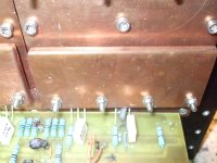
83/86 under the 4 mosfets those are clamped on the heat spreader with a cooper bar
Much more pressure than the single standard screwwuld alowd.
Almost 200W on each sink and themperature setles at 42 to 46 C (depending on ambient)
You could do much beter with air cooling a £4.5 Cheap and nasty CPU cooler quite happily dissipate 50W at slow (quiet) speed.
Water cooling maybe even better.
My personal experience is that they sound much better at hi bias hi voltagge
Run as well on 32 V and 3 A
I have not tried single( stock) so far.
Dinamics are realy good and very fast attack sound more open at 32 V rails.
You can bias the F5 as hi as your sinks alowd taking in consideration the thermal coupling
Papa reccomend 50 W device but with kerafoll and heath speders you may get better
Is all down to reliability how much of a risk you are prepared to take and how much you can afford to spend.
Diamond is the second best heath conductor (Graphene N 1) can you afford it.
I had quite same fun (not) lapping a cooper heat spreader to the sinks firs with carbide then warnish scratch remover and Bi carb of soda to the point that once cleaned up and dried the copper would stick to the sinks and have to slide the 2 off 2 take them appart.
The 2 are now bolted togheter with graphite based heat transfer paste and kerafol red
83/86 under the 4 mosfets those are clamped on the heat spreader with a cooper bar
Much more pressure than the single standard screwwuld alowd.
Almost 200W on each sink and themperature setles at 42 to 46 C (depending on ambient)
You could do much beter with air cooling a £4.5 Cheap and nasty CPU cooler quite happily dissipate 50W at slow (quiet) speed.
Water cooling maybe even better.
My personal experience is that they sound much better at hi bias hi voltagge
Wow, testing the Toshiba reliability?Got an F5 running happy at 26 V and 3.6 A on each rail with twin tosh (1.8 A each)
Run as well on 32 V and 3 A
Papa recomends 23.5V*1.3A= 30.5W 😎Papa reccomend 50 W device...
Is all down to reliability how much of a risk you are prepared to take and how much you can afford to spend.
Hi FLG
Sorry I cannot post Papa quote so you will have to trust me on this one.
His words where sometink of the sort "I would push the little ones up to 40W (To 220?)
And the big ones up to 50W (TO247)
So at 1.8 A 26 V is about 46.8 W continuous dissipation.
At my listening level with knob set on "she is gone out shopping and neighbours are out)
I get 12 V peak on my 4homs Pulke speakers at this point F5 leaves Class A
It runs happily for a few hours like this and sinks get up to 42 46 C
Main thing is to forget about the single screw and clamp them real tight Kerafoll graphs show that the performance increase with the pressure.
At the above conditions the temperature on the top of the case was about 63 C.
I tried the lower bias and had the impression that it was livelier at the higher setting.
I have also noticed an improvement on micro details while using the 32 V rails probably from the J fets.
Same as above Papa Quote from memory (the manufacturer have been a bit conservative in their specks they will take 35 V happily and 40 at a push)
Bias for the mosfets was at 1.5 A 48W so a total of 192 W dissipated by each of the sinks.
http://www.diyaudio.com/forums/swap-meet/182480-holco-mfr-15ppm-2w-sale.html
Well, naturally I was speaking of the Std F5 configuration. I beleive in ZV5 and maybe SOZ he did do 50-70/device. You can only get away with that if you have really good sinks and interface to them. As you are doing 😀 63C at the pkg top is excellent for those power levels.
It is a dangerous game though 😀
It is a dangerous game though 😀
Decent circuit protection take care of speakers.
Proper fuse of trafos.
I am still working on overcurent on the suply rails
and would need same help there
I am thinking about a mosfet as a switch to cut out the suply and a couple of comparators read the voltagge drop across the resistors on the CRC banks
Currents get up above certan limit so does the voltage drop across the resistors.
PS I do not use the onboard current limiters at the moment
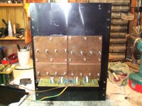
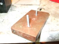
Overwiev of the heat sink and details (size is 300 X 400 X 83)
top set of screws for second board as byamping and possible balanced.
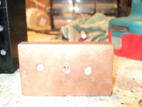
The earth block showing screw arrangment M4 at present M5 possible in a jffy(same on the heat sink)
This is as I do not like to strip the treads as loads of torque and repeat assembly
Proper fuse of trafos.
I am still working on overcurent on the suply rails
and would need same help there
I am thinking about a mosfet as a switch to cut out the suply and a couple of comparators read the voltagge drop across the resistors on the CRC banks
Currents get up above certan limit so does the voltage drop across the resistors.
PS I do not use the onboard current limiters at the moment
Overwiev of the heat sink and details (size is 300 X 400 X 83)
top set of screws for second board as byamping and possible balanced.
The earth block showing screw arrangment M4 at present M5 possible in a jffy(same on the heat sink)
This is as I do not like to strip the treads as loads of torque and repeat assembly
Attachments
I am having problems getting the dc offset down on one side of my new F5 build. With the bias at 59 the output dc is 130mv?? Any ideas
If it is positive offset you need a little more negative bias. Reverse if it is negative.
You will have to back off the positive side a bit - get it down by about 100mV and increase negative till it nulls out the balance.
Or is that something you've tried already?
You will have to back off the positive side a bit - get it down by about 100mV and increase negative till it nulls out the balance.
Or is that something you've tried already?
As Sangram said play with bias
that 59 is not written in stone
if your sinks can take it pump it up.
Got steady 2.5 mV dc offset after 3 4 hours of blissfull music.
that 59 is not written in stone
if your sinks can take it pump it up.
Got steady 2.5 mV dc offset after 3 4 hours of blissfull music.
Ok I got the offset down but very unsteady even after 2 hours of warm up. Sinks are fairly warm but not super hot, the offset jumps around between -20mv and + 30mv or so every time i get it down it jumps back up and won't hold. very fustrating
- Status
- Not open for further replies.
- Home
- Amplifiers
- Pass Labs
- What determines how high bias can be on F-5?