ASFAIK these cells are 1,2V each.
Still don´t follow you: What does the filament voltage have to do with bias?
Still don´t follow you: What does the filament voltage have to do with bias?
ASFAIK these cells are 1,2V each.
Still don´t follow you: What does the filament voltage have to do with bias?
Interesting question Lars, but not entirely obvious to the layman.
We have to measure the bias from one side of the filament or the other for a DC filament supply. In this case, the filament is specified as DC by the data sheet, so I assume that the plate curves are generated with DC heated filaments and that the negative for the filament is the reference side. If so, the 0V curve, is actually in positive grid bias.
I haven't really thought about this. But it should actually draw some amount of grid current. I'll have to go measure and see.
Sheldon
I haven't really thought about this. But it should actually draw some amount of grid current. I'll have to go measure and see.
And the answer is: Not much. I have a test jig I used for matching tubes. For this test, I have 30k on each plate and 80V B+. The filament is powered by a single D cell. The grid leak resistor is 825k. With the input open, I measure negative 35mV at the grid, 0V with a shorting plug on the input. That is a fraction of a uA.
I am using an MC step up with a 665 Ohm secondary. I cannot measure any voltage across that - not surprising, considering the grid current implied above. My meter can measure down to tenths of a mV, but that's all.
Sheldon
O.K. than please tell me, how is the circuit biased here:Still don´t follow you: What does the filament voltage have to do with bias?
Phono Preamplifier with 3a5 Directly Heated Triode
I would like to understand.😕
Tyimo
Interesting question Lars, but not entirely obvious to the layman.
We have to measure the bias from one side of the filament or the other for a DC filament supply. In this case, the filament is specified as DC by the data sheet, so I assume that the plate curves are generated with DC heated filaments and that the negative for the filament is the reference side. If so, the 0V curve, is actually in positive grid bias.
I haven't really thought about this. But it should actually draw some amount of grid current. I'll have to go measure and see.
And the answer is: Not much. I have a test jig I used for matching tubes. For this test, I have 30k on each plate and 80V B+. The filament is powered by a single D cell. The grid leak resistor is 825k. With the input open, I measure negative 35mV at the grid, 0V with a shorting plug on the input. That is a fraction of a uA.
I am using an MC step up with a 665 Ohm secondary. I cannot measure any voltage across that - not surprising, considering the grid current implied above. My meter can measure down to tenths of a mV, but that's all.
Oops! Typing without reviewing my thinking again. The grid will NOT be biased positive with respect to the cathode, if the filament supply negative is referenced to common. So no surprise that the grid current is very low. Sorry for any confusion.
Sheldon
O.K. than please tell me, how is the circuit biased here:
Phono Preamplifier with 3a5 Directly Heated Triode
I would like to understand.😕
Tyimo
In this example, the bias is a form of filament bias. The resistance of the filament supply itself is used to bias the tube. Let's break it down:
For V1 one terminal is taken from the middle of the common filament (pin 4). The other terminal is taken from the ends of the filament (pins 1,7), which are connected together. This is now two 1.4V filaments in parallel, but you can treat it as a single filament from here on. It doesn't matter which of the two terminals is connected to supply negative or positive. What does matter, is that whichever terminal is connected to the supply negative (battery or filtered DC), is also connected to common. If this is done, and the filament supply is 1.4V, then one end of the filament will be at 1.4V, and the common end will be at 0V. So the difference between the filament and grid, will be be a linear ramp from 0-1V. If you look at the plate curves, this represents the 0V curve. So the bias for this tube is considered to be 0V.
For V2, a second supply is stacked on top the supply for V1. So this filament is actually biased from 1.4 to 2.8V above common. We again take the negative side for our calculations, and call that 1.4V bias.
So, read no further until that is clear. If it's clear, there are some additional subtleties for this particular circuit.
There is a reason that Dmitry stacked the supplies. You could just connect the two tubes in series (each individual filament paralleled), and a single supply to either end of the series connection. But stacked, the supplies will isolate the tubes from one another. Otherwise the current from the output tubes will feed back via the cathode of the input tube. By stacking the supplies, there is a battery across each filament which shorts the ac through that filament, much like a capacitor.
Sheldon
Last edited:
Hi,
3A5/DCC90 are battery type filament tubes, in the 50s and 60s commonly used as transmitter o/p tubes mostly in 10meter (28 Mc ) equipment. Lots of those circuits in books of the period. One common circuit is that of a single valve remote control transmitter for model planes. See Electronics Australia, can't remember the issue.
3A5/DCC90 are battery type filament tubes, in the 50s and 60s commonly used as transmitter o/p tubes mostly in 10meter (28 Mc ) equipment. Lots of those circuits in books of the period. One common circuit is that of a single valve remote control transmitter for model planes. See Electronics Australia, can't remember the issue.
I'm thinking of direct coupling two 3a5 per channel to make a balanced preamp, with maybe Hammond 124b as outputs since I have some.
This would work for microphones or stage instruments. I need both myself - I need to make some recordings plus I'm a bass player.
andy
This would work for microphones or stage instruments. I need both myself - I need to make some recordings plus I'm a bass player.
andy
This would work for microphones or stage instruments.
The tubes as microphones is what you will have without great care. Not sure I'd mess with DHT's for high gain stage amps. Lots of vibration in that environment.
Sheldon
hehe...I built a boost pedal with these tubes, and it sang like a trumpet when cranked due to feeding from the sound of the cabs. That was my only real attempt at using these tubes for anything other than experiments. Mounting the tube on an elastic mount helped, but even then it feeded when cranked.
I was thinking of encasing the tubes in concrete and burying them in the ground. Well, maybe a flower pot so I could take it on stage.
Tyimo,
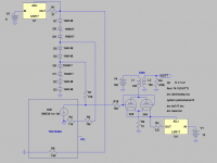
The section on the bottom right of my phono amp schematic is the current source I'm using. It's actually simpler than it looks, only 5 transistors, and performs very well. The ZTX and MJE Darlington pair form a simple cap multiplier, that feeds a diode biased current source. The BC transistors are wired as diodes to bias the 2SA1887. I used what I had in my parts bin, so lots of different possibilities for parts. But the 2SA part is a nice one for this. I'm using one cap multiplier to feed two CCS's (one for each channel).
Sheldon
Sheldon
I wouldn't like to use CCS. Sorry.
Tyimo
Which scematic do you mean??The section on the bottom right of my phono amp schematic
I wouldn't like to use CCS. Sorry.
Tyimo
Tyimo,
Did this design quite a while ago for my friend Bardis who built it and showed it with great succes at our yearly DIY-fest.
Bardis decided to use a DN2540 circuit on top to get low Zout. Have schematic somewhere in my computer.
I don´t remember, but the figures for the DAC where decided after a discussion with Thorsten L. here at diyaudio.
R2 is choosen to give the right bias with 220ma going through it. Ia somewhere in the ballpark of 9mA for both halves together.
Last edited:
Sheldon
Which scematic do you mean??
I wouldn't like to use CCS. Sorry.
Tyimo
Forgot to post the link: http://www.diyaudio.com/forums/atta...99104-unholy-alliance-phono-amp-3a5-phono.jpg
Not sure it matters, given your stated preference.
Sheldon
Thanks Lars!R2 is choosen to give the right bias with 220ma going through it. Ia somewhere in the ballpark of 9mA for both halves together.
- Status
- Not open for further replies.
- Home
- Amplifiers
- Tubes / Valves
- What can you do with a 3a5?