Hello again
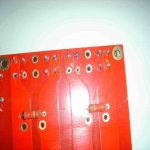
Whilst soldering two of the diodes I found the solder did not bond with the PCB (dirty contact). I ended up by applying too much heat to the board and have ended up damaging the copper pad.
Can I carefully solder this diode on the component side? Or is there a way of repairing the contact.
Tripmaster
Attachments
Hello Tripmaster - you are looking for a circuit repair kit that is somewhat like this - http://cgi.ebay.com/PACE-CIR-KIT-Pr...ryZ36327QQssPageNameZWDVWQQrdZ1QQcmdZViewItem
This kit is for repairing circuit traces as well as plated through holes and from reading your description I think the only thing you will need is the eyelet repair part of the kit. The one listed is in USA so you are most likely better off looking for something in GB - (although the dollar is low). Take a look at the photo's in this ad and you will see one of them that shows an eyelet being set into a PWB. Not difficult with the proper tools and a gentle touch. Hope this helps
This kit is for repairing circuit traces as well as plated through holes and from reading your description I think the only thing you will need is the eyelet repair part of the kit. The one listed is in USA so you are most likely better off looking for something in GB - (although the dollar is low). Take a look at the photo's in this ad and you will see one of them that shows an eyelet being set into a PWB. Not difficult with the proper tools and a gentle touch. Hope this helps
Tripmaster. I have one of these Chipamp.com boards. If you look at the track to which the diode is attached, you will see that the diode above it (on your photo, and next to the board edge), one leg is connected to the same track. Just solder a wire from the (right, according to your photo) leg and the right leg of the diode above. That leg of the diode will not be attached to the board,but it will still work.
Alternatively just scrape away some of the lacquer on the track to expose the copper track and connect a piece of wire from the exposed track to the leg.
Where in Hampshire are you ?
Alternatively just scrape away some of the lacquer on the track to expose the copper track and connect a piece of wire from the exposed track to the leg.
Where in Hampshire are you ?
Tripmaster. I am about 30 mins up the A3. If you can't get it sorted, perhaps we can get together ?
The other side of Haslemere.
Here is what I suggest you try
http://i73.photobucket.com/albums/i239/saxonsex/ChipBD.jpg
Here is what I suggest you try
http://i73.photobucket.com/albums/i239/saxonsex/ChipBD.jpg
Thanks Puffin
Should I use the same wire that I plan to connect the PSU to the amps? I think it's 0.4mm
What have you used for your enclosure? I have two 300va 2x25 transformers
Should I use the same wire that I plan to connect the PSU to the amps? I think it's 0.4mm
What have you used for your enclosure? I have two 300va 2x25 transformers
Hi,Tripmaster said:I have two 300va 2x25 transformers
is that 230:25+25Vac or 240:25+25Vac?
You are getting very close to maximum ratings for 8ohm speakers.
What is the maximum PSU voltage when the mains is @ 254Vac? i.e. +6% tolerance.
I believe they are 230v 300va 25+25 with a typical regulation of 6.5%
More info can be found here www.clairtronic.com/toroidal.pdf
More info can be found here www.clairtronic.com/toroidal.pdf
Tripmaster. I use the Clairtronic trannys from Rapid. Seem fine to me.
Any wire will do.
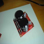
This is my enclosure.
http://i73.photobucket.com/albums/i239/saxonsex/BlueLeds.jpg
http://i73.photobucket.com/albums/i239/saxonsex/AmpBack.jpg
Homebase Bread Bin !
Any wire will do.
This is my enclosure.
http://i73.photobucket.com/albums/i239/saxonsex/BlueLeds.jpg
http://i73.photobucket.com/albums/i239/saxonsex/AmpBack.jpg
Homebase Bread Bin !
I have been trying to solder the diodes this morning but the solder still refuses to bond with the pcb. I have lightly sanded the contact on the pcb and diode and wiped with pcb & flux cleaner.
What am I doing wrong? I don't seem to be able to tin my iron tip.
What am I doing wrong? I don't seem to be able to tin my iron tip.
Hi,
your tip should not be iron (Fe). It is more likely to be plated copper.
Some tips are plated with a chemical that should not be sanded/filed/ground as this then makes them impossible to tin (coat with solder).
Can anyone tell whose tips are which type and which are easily tinned?
your tip should not be iron (Fe). It is more likely to be plated copper.
Some tips are plated with a chemical that should not be sanded/filed/ground as this then makes them impossible to tin (coat with solder).
Can anyone tell whose tips are which type and which are easily tinned?
some are iron plated, but I think these cannot be tinned in their raw state.
They may have nickel over iron on copper.
They may have nickel over iron on copper.
Tripmaster. If you are trying to solder the wire to the (now non existent pad) It is not going to work. Have I read you correctly ? "the solder refuses to bond to the pcb", it won't as the solder point has gone. As for getting your soldering iron to work correctly, can you post some close ups of the tip ?
Inside of the Bread Bin
http://i73.photobucket.com/albums/i239/saxonsex/AmpInternal.jpg
Inside of the Bread Bin
http://i73.photobucket.com/albums/i239/saxonsex/AmpInternal.jpg

Hi,
The lack of tinning on the tip may be a clue.
The other is that the small pads have soldered pretty well.
I think the problem is lack of equal temperature in the component and pad, particularly when the pad has a large sink connected to it.
Try getting that tip tinned, or use a new tinned tip.
Apply a little solder to the tip and use this to heat the pad adjacent to the component leg. Roll the tip in towards the component and apply heat to both sides of the joint.
Touch the cored solder to the component and the heat should pull the molten pool all the way down to the pad.
The important points are that both sides ot the joint must be hot and both must be clean.
- Status
- Not open for further replies.
- Home
- Amplifiers
- Chip Amps
- What a doofus!