thanks for the heads up, I won`t be touching any other part of the speaker.
from watching videos and reading through the few threads here about replacing the surrounds, I believe I should be alright, its just a matter of getting the correct pieces.
even if they're generic and need cutting to size that shouldn't be an issue. bit the dimensions of the curved part would still need to be pretty good, which is why i'm worried about buying generic. i understand that the generic ones still need to be installed upside down on the wharfedales, so the dome is concave but finding something that is within 2mm of the required circumference when there seems to be about 10 different styles is whats getting to me when choosing an exact generic.
If you look at the replacement surround of the left hand 3014 in my attachment, you'll see joins at 9 o'clock and 3 o'clock where sections cut from a larger diameter surround have been glued together.
Do let us know if you find a similar solution.
Do let us know if you find a similar solution.
I know you guys have used old tire tubes and all sorts to fix your speakers, I'm not at that stage of improvising yet, I've contacted a few places and ordered a set of generics from a US supplier.
I got word back from a couple of local stores here in Montreal, but they only forwarded me a few sites i've already contacted, its a shame they didn't have parts suitable in stock.
so far i need to hope the generic i ordered is good. but it will take weeks to get delivered here.
I got word back from a couple of local stores here in Montreal, but they only forwarded me a few sites i've already contacted, its a shame they didn't have parts suitable in stock.
so far i need to hope the generic i ordered is good. but it will take weeks to get delivered here.

In my quest to repair these speakers,
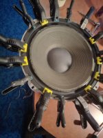
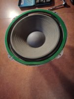
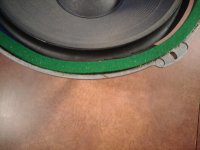
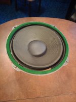
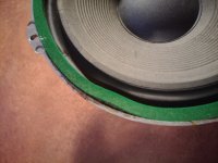
I got some generic surrounds (rubber) from Amazon faster than the US supplier, so I went and got them changed.
I also checked the crossover and seen that the 25mf capacitor was done as was one of the midrange speakers, i changed the capacitors out for a 10 +15mf and on a blind test the new caps sound better than the old so i'll change out the other too to match, i cannot tell for sure if its better sounding because of the midrange speaker thats totalled in the other speaker, so i'm going off memory of that speaker playing solo before the change.
I found a replacement set of mids on Ebay, i'm currently bidding on, I hope i get them.
but if for any reason i'm outbid and cannot find a working replacement midrange, does anyone have any recommendations for replacement speakers? i would change out the two 5" midrange speakers for another set of similar (preferably better) sounding speakers.
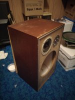
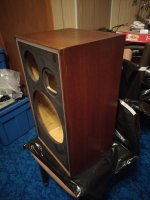
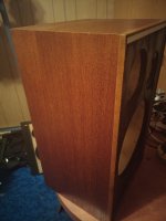
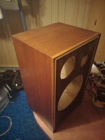
I took a bunch of pics during my refoam and wood restore results, I'll post them up when I'm all done. with my poorly setup amp for the moment, i'll be getting a nicer cabinet later, and plan to build a copy of the wharfedale dovedale speaker stands but in wood to give it the same look. i also sprayed the front wood black to look a little more like the 1973 model, my wife and friends think it looks alot better, I'm also planning to add little plugs to the screen to easily take them off.
I actually wanna completely rebuild the crossovers, but I'm waiting for an order of silver based solder to arrive i'll take a gander at re doing the cross over when i get everything.
But aye. any idea what the best replacement for the midrange speakers would be?
I got some generic surrounds (rubber) from Amazon faster than the US supplier, so I went and got them changed.
I also checked the crossover and seen that the 25mf capacitor was done as was one of the midrange speakers, i changed the capacitors out for a 10 +15mf and on a blind test the new caps sound better than the old so i'll change out the other too to match, i cannot tell for sure if its better sounding because of the midrange speaker thats totalled in the other speaker, so i'm going off memory of that speaker playing solo before the change.
I found a replacement set of mids on Ebay, i'm currently bidding on, I hope i get them.
but if for any reason i'm outbid and cannot find a working replacement midrange, does anyone have any recommendations for replacement speakers? i would change out the two 5" midrange speakers for another set of similar (preferably better) sounding speakers.
I took a bunch of pics during my refoam and wood restore results, I'll post them up when I'm all done. with my poorly setup amp for the moment, i'll be getting a nicer cabinet later, and plan to build a copy of the wharfedale dovedale speaker stands but in wood to give it the same look. i also sprayed the front wood black to look a little more like the 1973 model, my wife and friends think it looks alot better, I'm also planning to add little plugs to the screen to easily take them off.
I actually wanna completely rebuild the crossovers, but I'm waiting for an order of silver based solder to arrive i'll take a gander at re doing the cross over when i get everything.
But aye. any idea what the best replacement for the midrange speakers would be?
I've not come across any suggestions as to substitutes for the Dovedale III mids, the characteristics of which are of course unknown.
They do crop up at auction from time to time (I sold a pair a couple of years ago).
Let's wait and see if your bid is successful.
They do crop up at auction from time to time (I sold a pair a couple of years ago).
Let's wait and see if your bid is successful.
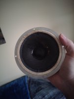
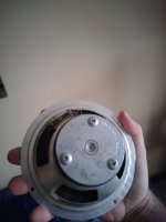
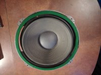
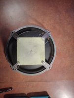
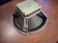
For reference, here are photos and dimensions of the Dovedale III midrange driver.


The mid is a 130 mm (5") unit with a chassis diameter of 145 mm (5.75").
The mid is a 130 mm (5") unit with a chassis diameter of 145 mm (5.75").
I realise something, the speakers you posted are the same as the bid i'm currently waiting for, but these speakers are the 4 ohm version from another model speaker.
my 1971 speakers have a smaller round magnet, and are 6 ohm. I will need to add a resistor in line to limit these 4 ohms down to 6 when i get them setup to match the crossover power limits correct?
my 1971 speakers have a smaller round magnet, and are 6 ohm. I will need to add a resistor in line to limit these 4 ohms down to 6 when i get them setup to match the crossover power limits correct?
my 1971 speakers have a smaller round magnet, and are 6 ohm.
Please post a photograph of your mid driver (front & rear).
Perhaps the seller of the mids you are bidding on has quoted their resistance as 4 ohm, which would equate to a nominal impedance of 6 ohm?
the bidder posted images of his digital multimeter rating the 2 speakers at 3.8 ohm so i took that as 4 ohm speakers.
checking mine before i got a reading of 6.3 from the working speaker and nothing on all contacts from the other, i also placed the multimeter on the solder points on the backside of the cone to see if the wire contacts to the PCB where broken, but no dice either on them.
checking mine before i got a reading of 6.3 from the working speaker and nothing on all contacts from the other, i also placed the multimeter on the solder points on the backside of the cone to see if the wire contacts to the PCB where broken, but no dice either on them.
Attachments
the bidder posted images of his digital multimeter rating the 2 speakers at 3.8 ohm so i took that as 4 ohm speakers.
This indicates the seller's mids have a nominal impedance of 6 ohm which should be compatible with your crossover.
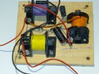
Post a photo of the crossover board if convenient.
That's the one I expected, just wanted to be sure.
The crossover is uncomplicated and should be tolerant, within reason, of mid driver nominal impedance value.
Remember that the Dovedale III crossover was 'tuned' back in the old days before precise computer modelling.
The crossover is uncomplicated and should be tolerant, within reason, of mid driver nominal impedance value.
Remember that the Dovedale III crossover was 'tuned' back in the old days before precise computer modelling.
one of the crossovers (the working one) i changed out the 25uf capacitor with a new 10 and 15uf, i would have liked to test it against my other speaker but without the mid its not fair, haha.
the 10 and 15 caps i got are not greatly well placed, and is why i really want to sit down right and rebuild the placing of the crossover. but as it is it works alright. i'll do the same thing with the other, but i want to find a replacement for the 6uf before i open them again, my local shop didn't have the right values, the best they had was a 5 at 40v i didn't want to replace with a cap of a lower value.
i'll drop by a few place before work tomorrow to see if i can get a 6uf at 50v to replace the other caps on both units. and get back here.
I'll post a few pics of my work and my setup. it's not complete yet.
Attachments
-
 2024-11-04-13-08-24-342.jpg445.7 KB · Views: 43
 -
 2024-11-11-23-57-18-021.jpg471 KB · Views: 44
 -
 2024-11-11-23-58-16-761.jpg423.6 KB · Views: 40
 -
 2024-11-15-00-09-45-639.jpg467.6 KB · Views: 45
 -
 2024-11-15-00-12-24-212.jpg429.1 KB · Views: 42
 -
 2024-11-17-16-13-03-823.jpg619.7 KB · Views: 46
 -
 IMG_20241124_170641_01.jpg70.4 KB · Views: 47
 -
 2024-11-03-15-17-46-170.jpg399.4 KB · Views: 50
 -
 2024-11-03-15-17-35-327.jpg370.4 KB · Views: 42
 -
 2024-11-03-15-17-40-698.jpg445.4 KB · Views: 42
 -
 2024-11-03-15-17-29-845.jpg415.3 KB · Views: 42
 -
 2024-11-03-15-17-24-405.jpg420.1 KB · Views: 41
 -
 2024-11-03-15-17-05-295.jpg405.5 KB · Views: 40
 -
 2024-11-03-15-16-15-645.jpg407.6 KB · Views: 43
 -
 2024-10-30-13-14-43-328.jpg476.2 KB · Views: 47
...to see if i can get a 6uf at 50v
Standard value 5.6 uF would do just fine and a higher working voltage is quite permissible.
I can get a 6.0 uF and 25 uF bipolar electrolytic capacitors over here - from the Mundorf Ecap Plain (smooth aluminium) range.
P.S. Thanks for the pics. Those surrounds were really gone!
Thanks again,
Canada is in a bit of stuck problem with postage, only amazon is still doing deliveries. Canada post is on strike as is the main port workers of montreal. so getting anything delivered before xmas would be a miracle. there is a few weeks of backlog now piling up so i doubt anything will be going or coming for some time. so it's why i'm trying to look locally, there is a bunch of electronics stores that sell components, i just have to do more spelunking. i only looked in my local area, i've not gone to the west side of the island or even more north were there are other stores too for electronics.
I have many options, just not the free time. haha. i work on the speakers at the weekends when i'm free or for an hour or so after work. but when i'm finished work the shops are closed, so i got to plan more in the mornings to run about. i'll be in central montreal tomorrow anyway for other things so i'l drop by some stores to see if they have anything i can use.
- Home
- Loudspeakers
- Multi-Way
- Wharfedale Dovedale 3