Don't ask me, I'm sceptical of of everything until I can verify if it matters for me! I have no idea if carbon fibre is better than common materials. My take on it is that very few people will hear any difference, but a lot will claim to hear it😉
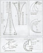
Finally i have gotten sato horn drawing
Couldn`t get it from anyone, so tried to upscale image using photoshop and result impressed me
images will be attached below, maybe someone will need it
I will need to make an adapter from 2`` to 0,71``. how long it will be?
I should make it straight or curved?
Thanks.
Couldn`t get it from anyone, so tried to upscale image using photoshop and result impressed me
images will be attached below, maybe someone will need it
I will need to make an adapter from 2`` to 0,71``. how long it will be?
I should make it straight or curved?
Thanks.
Attachments
Andrew,I will need to make an adapter from 2`` to 0,71``. how long it will be?
I should make it straight or curved?
Thanks.
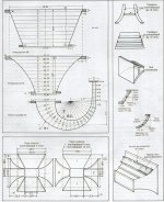
The throat size of that horn may only be 1.5", the round to square part shows a square tube being beaten to the size of a 40mm pipe.
The continuation of that flare reduction could be straight, though to reduce down to .71 inch, the driver would probably end up in front of the mouth, the adapter would probably be over 10 inch long.
GM's post #10 here gives some idea as to how to figure more exactly:
Western Electric 15A Small SATO horn
Cheers,
Art
Still collecting more information about thisVery nice. Thanks for posting those.
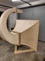
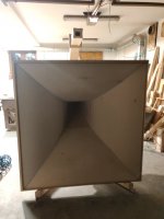
Will you be building a pair of these?
It is very expensive project for me, so i need to be confident in my decision
First, i`m still looking for original plans of horns for 0.71`` driver.
Second, i need to know what type of sandwich(how many layers of plywood, type of material between them etc) should i use
Thanks, you have read my mind, i really don`t want to see driver closer than horn, especially if distance is about 35cmAndrew,
The throat size of that horn may only be 1.5", the round to square part shows a square tube being beaten to the size of a 40mm pipe.
The continuation of that flare reduction could be straight, though to reduce down to .71 inch, the driver would probably end up in front of the mouth, the adapter would probably be over 10 inch long.
GM's post #10 here gives some idea as to how to figure more exactly:
Western Electric 15A Small SATO horn
Cheers,
Art
The plans you posted - which I have not seen before - are for metal construction. Basically 0.8mm sheet metal soldered together. The "mastic" is putty used to damp the metal resonances. Window putty is normally used. Blackson was a tar based putty that didn't harden. Genuinely horrible stuff to handle, but it works well to kill vibrations.
You'll want plywood that you can bend, I'll dig around for other plans to see what thickness was used. If the plywood is thin enough to bend, it will need vibration damping too.
You'll want plywood that you can bend, I'll dig around for other plans to see what thickness was used. If the plywood is thin enough to bend, it will need vibration damping too.
Hmmmm... Maybe. There was a nice fellow named Carlo years ago who built replica 15A horns. I think I remember him saying that the published plans were not 100% correct.
You might want to do a test run or maybe two with cardboard to be sure.
You might want to do a test run or maybe two with cardboard to be sure.

- Home
- Loudspeakers
- Multi-Way
- Western electric compression driver clones