Well said.I find auto transformers interesting in a crossover.
For the purposes of regaining control, you could reverse engineer the response to replace it with other components. You'd measure the driver Voltage and the driver impedance, then use a simulator to find alternatives.

Thank you, you've helped me more that you think!
Many thanks to all the people who posted on this thread!
Many thanks to all the people who posted on this thread!
Well said.
For the purposes of regaining control, you could reverse engineer the response to replace it with other components. You'd measure the driver Voltage and the driver impedance, then use a simulator to find alternatives.
This is why I like autotransformers 🙂
Let's assume the autotransformer is set up for -4.4db, and .21mh shunt inductance. Now let's convert it to a conventional third order high pass with the tweeter attenuated 4.4db.
The reflected load on the parallel 1uf capacitors is 2.78 times the actual load (100/60)², so the first thing to do is replace those capacitors with a total of 2uf X 2.78 or 5.5uf. Next we replace the autotransformer with a shunt .21mh inductor. We leave the 6.8uf capacitor as is, and add a -4.4db LPad to the tweeter...3.18Ω series and 12.13Ω parallel. I simulated these circuits in LTspice, and the result is spot on.
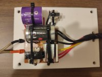
The coil doesn't look particularly weird. It's just a stack of E-laminations with the coil on the center leg.
The stray flux from the choke will be directed from the center leg of the core to the two outer legs, so the stray flux emanated for the inductor will be directional, unlike an inductor wound on a stack of "I" laminations or a ferrite bar, which will spray flux all over the place like a dipole. The lack of the I-bar component to close the magnetic path introduces a large air gap, which will help linearize the the inductance vs. current characteristic of the core. However, silicon steel has a very square hysteresis loop, so when you finally pump enough current into the inductor to saturate it (given the gap size, a lot of current), the core will saturate all at once. You could also play a trick like this using 1/2 of a ferrite pot core.
The stray flux from the choke will be directed from the center leg of the core to the two outer legs, so the stray flux emanated for the inductor will be directional, unlike an inductor wound on a stack of "I" laminations or a ferrite bar, which will spray flux all over the place like a dipole. The lack of the I-bar component to close the magnetic path introduces a large air gap, which will help linearize the the inductance vs. current characteristic of the core. However, silicon steel has a very square hysteresis loop, so when you finally pump enough current into the inductor to saturate it (given the gap size, a lot of current), the core will saturate all at once. You could also play a trick like this using 1/2 of a ferrite pot core.
@mboxler
That looks awesome and pretty straightforward. The only problem that I see is the given values for the components - 5.5 cap, 3.18 and 12.13 resistors.
The closest values that I could find are 5.4 or 5.6 uF caps, 3 or 3.3 ohm, as single components. Would it be ok to use 2 caps in parallel 5.4 and a 0.1, and 2 resistors in series 3 and 0.18/12 and 0.13 ohm to get to the desired values? What wattage need the resistor to be? What DCR should the coil have?
I will need to source the missing parts but will definitely give it a go.
@wrenchone
The weird part is that it has 2 independent wires / 4 ends and and connects to the PCB in 3 different spots, opposite to a standard coil, a single piece of wire with just 2 ends.
My simulation was based on the assumptions that the A - B inductance is .09, -4.4db attenuation, and an 8ohm tweeter.. We still don't know what the values of your autotransformer are or the impedance of your tweeter. I'd just replace the capacitors and leave everything else alone to begin with. Or, at the very least, pull and measure the coil from the other speaker just to make sure they are the same. Also measure the DCR of your tweeter.
If you are the adventurous type, 3.3ohm and 12ohm resistors (8 ohm tweeter, 5 watt resistors) and a 5.6uf capacitor will work just fine. As for the inductor, I would just reuse the autotransformer. Leave the A wire floating, solder B and B1 to B, solder C to C, and solder a wire between A and B on the pcb. If you do want to use a .21mh inductor the DCR should be close to the DCR between B1 and C on the autotransformer, but I wouldn't worry too much about that.
Again, I would just replace the capacitors as a first step. Replace one 1uf capacitor with a 2uf and leave the other 1uf spot empty. Later you could put a 3.3uf in the second spot to give you 5.3uf which is still fine for your conversion.
- Home
- Loudspeakers
- Multi-Way
- Weird crossover coil