There is a switch on card's rear for coax-opt selection.
If a USB daughter card is present, its input is automatically selected when the USB cable is plugged in.
If a USB daughter card is present, its input is automatically selected when the USB cable is plugged in.
I d like to place switch offboard, on front panel, but it will require long wires. If switch is in place of the signal, I should possibly consider using relays , this would eliminate interference threat and keep signal clean ?
hi Vox,
have you considered what mods you are going to do? Apparently my DAC has arrived and I shall collect it tomorrow,
stu
have you considered what mods you are going to do? Apparently my DAC has arrived and I shall collect it tomorrow,
stu
Is it a direct swap or will I need to change some of the surrounding circuitry?
(...)
If I make an order from digikey UK or Farnell I will need to pay a one off postage fee.... what would be your first suggestion for extra components to change, I don't want to do too may mods but I would be comfortable replacing a few bits...
Hi Stu,
I've missed your questions... but better late than never.... 😉
The LME49710 is a direct replacement, no mods to support it.
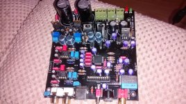
The first things to replace are the PFRs (blu boxes) and the green EROs, along with the Samwha smoothing caps (unless the vendor changed brand)
Not really. My one is coming.
I will follow Dario's route, I trust him a lot for a good reason- if you follow his advise it will always be clear and tidy. If no, people here will help.
So if you re planning to mod, we can make a list of parts to buy.
I will follow Dario's route, I trust him a lot for a good reason- if you follow his advise it will always be clear and tidy. If no, people here will help.
So if you re planning to mod, we can make a list of parts to buy.
Hey guys, what are you using for a power supply? I might pick this up with case and do upgrades on it later.
I ve got board now.
It is version 1.2 , with evox pfr caps.
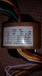
How to wire transformer:
Mains, 4 wires : 0 (blk) 115 (grn) 230v (red) SGN (yel/grn)
And secondary: 2 white (0v 9v) 2 yellow (0v 15v) 2 blue (0v 9v) 2 brown (0v 15v)
I ve seen wiring pic, from left to right: 2 white, 2 blue, 2 brown , 2 yellow
Question- with each pair there is no difference, which goes left or right ?
Thank you
It is version 1.2 , with evox pfr caps.
How to wire transformer:
Mains, 4 wires : 0 (blk) 115 (grn) 230v (red) SGN (yel/grn)
And secondary: 2 white (0v 9v) 2 yellow (0v 15v) 2 blue (0v 9v) 2 brown (0v 15v)
I ve seen wiring pic, from left to right: 2 white, 2 blue, 2 brown , 2 yellow
Question- with each pair there is no difference, which goes left or right ?
Thank you
Attachments


Question- with each pair there is no difference, which goes left or right ?
Each pair (same color) is a secondary.
For 15-0-15 input you should use brown, brown/yellow tied together, yellow.
Just for sake of security measure AC voltage between the brown/yellow and brown and yellow, you should read 15Vac each time.
Looks like black is neutral, green to be wired together with red to get 230 and sgn is ground?
No, for 230V operation green must be isolated, black neutral, red phase.
Yellow/Green is transformer's screen and should be grounded.
Good afternoon.
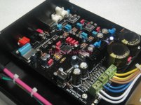
Thank you Dario.
Like in this (yours) pic.
Thank you Dario.
Like in this (yours) pic.
Attachments
Last edited:
Good afternoon.
Thank you Dario.
Like in this (yours) pic.
You should measure 30V AC end to end. If not, one of rail is out of phase. To make them in-phase, just switch one of legs (brown OR yellow) for making 0V. Then you should measure 30V rail to rail.
Thank you
Question:
I have enclosure ready for another dac, and all cut outs already in place, except usb.
Can I use existing receptacles (rca's not a problem, I know)?
I mean, if I use toslink receptacle from twisted pear: TOSLINK Optical Input Module instead of existing, or I can lift existing and wire remotely (it might fit existing cut).
As well, I d need to do do the same with usb (for instance PX0447 - BULGIN - MINI USB TYPE B, RECEPTACLE, PANEL | Farnell UK )
And on top of the things I would like to place spdif switch on front panel, for easier access, but wires will be long. Will it affect sound, or interference risk ?
🙂
Keep in mind that modifications may be more difficult to accomplish with the hard wired sockets and receptacles for your signal in/out.
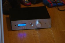
I do admire your path of making a device that would pass as a consumer product though.
Mine started like that, but now looks like robot war/lampizador, experimental-thing on the inside of the case anyways.
Did you get the transformer wires sorted out?
How big is the enclosure? Is it ventilated?
I do admire your path of making a device that would pass as a consumer product though.
Mine started like that, but now looks like robot war/lampizador, experimental-thing on the inside of the case anyways.
Did you get the transformer wires sorted out?
How big is the enclosure? Is it ventilated?
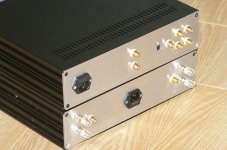
It is 330x280, galaxy enclosure from modu shop, italy. It is partially vented. Another device in there is small pre board.
I ll keep usb in place, just use panel mount receptacle and short usb cable to it for now.
Only problem is toslink module....
Cases look a bit different- polished and so on.
I will be submitting another cnc project for back panel- I need to redo allocation of jacks and iec on pre back panel, it has to be the other way around, but it will take time, as I m doing it via my friend,and these things never happen easy 🙂
Attachments
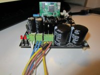
Re front panel switch: you can see there is a hole, I can use for switch, but it means running wires back to front (in current setup it will have to cross mains wire 90' once, so I ll possibly redo back and move iec to the other side).
Possible solution is to use relays to switch signal?
Possible solution is to use relays to switch signal?
That case is nice!
I wonder if the relays that would be good for replacing that switch would fit in it's place?
Would seem to be better than running coax all over, maybe.
Can you manage the room to ba able and partition the transformer in a separate chamber?
I wonder if the relays that would be good for replacing that switch would fit in it's place?
Would seem to be better than running coax all over, maybe.
Can you manage the room to ba able and partition the transformer in a separate chamber?
Possibly yes. But I think I ll just ask my friend to do new back panel. This way iec and transformers will be far from signal wires
- Status
- Not open for further replies.
- Home
- Source & Line
- Digital Source
- Weiliang DAC9 with AK4399