Hello,
I will copy and paste some post i wrote in this section of the diy.audio.com website
Hello,
I think Andrea and Ian should join and write a kind of '' tutorial '' HOW to combine their creations together in the best way.
I honestly think that spreading all ( number is getting bigger each '' upgrade'') the boards in an almost randomly way is not the right way. Usually it will be done in a non logical way because the extra board will be positioned in an area that is not occupied yet on the wooden panel.
A bit like tuning your car engine with a bigger cylinder which forces you to a add a trailer to your car because it doesnt fit where it needs to be. BUT all your friends can see you had the guts to get the thing everyone is talking about.
Very few people will question if this improvement is a real one .
Maybe there is someone who removed the original cylinder and took it to his friend who has a nice CNC milling/router machine to add only 25 % of the CC increase the big one is offering BUT because it stays where it should be it gives the same improvement without the use of a trailer.
There should be a bit more guidance. I am sure there are boards that care a lot about the length of its power supply cable while others dont mind that much.
The I2S cable MUST be short that is carved in stone.
Some cables should only cross at square angles?? Just like a hardwired tube amp there are some rules.
But here everything digital and no buzz from heaters everyone seems to do things like there are no rules. There must be or not?
Greetings, eduard
Hello,
Once more it looks like getting the best results also depends a lot on the '' physical postion '' of ALL the elements you will end up needing in a DDDAC unit with fifopi, raspberry, supercap, lifepo4 all combined INSIDE one chassis.
The stationpi board from Ian is a good start to have fifopi and raspberry properly connected AND also offering reduction of mutual '' interference '' while still being close.
I will kind of '' develop '' a construction that will allow the lifepo4 board to be mounted under the station pi and allow the use of several ultracap boards that will All end up with a short connection to the lifepo4 board and the 5 and 3,3 volt dc input and all the boards. Mounting everything on the '' same level '' will create to much surface to be needed and long wires all over the place. I think from a technical point of view these items should be mounted inside a metal frame.
My idea of giving each board a separate lifepo4 and supercapboard was to get maximum separation by not letting them same the same supply.
The 6 clock boards from Andrea will be in a collection of six aluminium so called stomping boxes because they are very likely to interfere when being in the same chassis as the rest. The physical distance between the stomping boxes and the BIG DDDAC chassis wont be big but there is a lot of metal in between them.
Greetings, eduard
Hello,
Of course the 3000F can offer some benefits if it can be used without being connected to the electricity coming from the wall.
BUT if you count the number of crimping, soldering and "" sliding " contacts i wonder why nobody tries reducing that number. Once you know where exactly the UcHybrid board will be positioned in relation to the lifepo4 cell there will be room for improvement. WHY not solder a cable at both ends to connect the cell to the supercaps..i think the big number of contacts between these two parts will do more damage than a bit more cable. But of course if you can use 3 inch, 8 centimeters good cable directly soldered why not.
If you use the supplied cable it will cost you nothing. .
Greetings,Eduard
Hello,
I think that adding this seize/weight of caps to the already big collection of boards on a wooden panel like we can see here usually will be downright dangerous. These caps need to be attached in a proper way, no tie raps, instant glue, silicon kit or duc tape.
Greetings, Eduard
SO wouldnt it be nice if someone wrote a down to earth kind of tutorial how to do things right. A bit like the sticky about heater wiring in tube amps.
I am sure one of the experts here could spend some time on a do's and don't list regarding the '' composition '' of a collection of a large number of boards and make these work like a team.
If they are only aiming to let us buy another board with more F while placing your '' tiny '' F boards closer to your fifopi would give more improvement than buying something that has to be mounted even further away than your tiny board. Sure most of us will be crazy enough to buy it convince others it is an improvement because much more F . Probably it will indeed sound better even when the cable is even longer than with the tiny F board. But it is the wrong way to do things. We pay extra and will only get a minimal part of the improvement compared to doing things the perfect way.
BUT when Doede, the DDDAC man told us about a design to safely use big F caps the most clearly expressed advice to put the supercap CLOSE to the board where the power is needed. While here we end up using bigger F caps not with a 20 cm cable but with a 40 centimeter one while we should have done everything to make it able to start with a 10 cm cable or less.
Greetings, eduard
Maybe you can set up a GoFundMe or other money collection operation, to ensure that the people who do all of this work are paid for their time?
Hello,
Maybe,
But dont forget how much time these experts spend here promoting their own products.
So you could consider it as a kind of aftersales.
Just persuading your customers to replace their 9 months boards with their latest baby is just like a commercial business strategy.
Greetings, eduard
Maybe,
But dont forget how much time these experts spend here promoting their own products.
So you could consider it as a kind of aftersales.
Just persuading your customers to replace their 9 months boards with their latest baby is just like a commercial business strategy.
Greetings, eduard
A good start could be a building thread with a first post with the link towards :
the different pdf and building threads, BOM towards the different generation of the two designers...
the different pdf and building threads, BOM towards the different generation of the two designers...
Hello,
It can be done in several ways.
Lots of de pdf contain useful information but once you are kind of finished the board you dont need all of it
Most of the questions and problems arise once you need to start connecting the boards together.
I2S connection needs to be short.
Connection from supercap board to circuit board must be short ( this one that i imposed myself)
Use split bobbin power transformer and choke input power supply. Of course most engineers will tell you their supply is so good there is no need to use a choke and any transformer will do.
Which boards cannot be close to each other.
Which boards cannot be close to a power transformer
Which boards could work better with grommets to reduce vibrations.
Which standard cables can be replaced by better ones.
Greetings, eduard
P.s Clear instructions will persuade more people than arguing about measuring clocks
This makes you smile,lol : yesterday I looked at the former Discrol board (so first gen.) and I didn't understand how by the hell it could be pluged on a DIL socket the size of the Crysteck clock : looking for the vias for leads to be soldered I saw only 3 or something certainly I didn't understand from the casual firt look ! I have to find again by clever digging the post where the pdf of the boards are !
I'm trying to explain and convince Rogic to make room on his new AYA5 DIY design for versatility in order to plug the former Andrea's pcbs as the new ones seems a lost cause due to the squarrer size... and I fear not to sucess in this puzzle you highlighted !
At least, the former littlefirst gen. board adaptor with the sma and uf-l connector seems ok, but how good vs a local crystal directly soldered on the dac pcb ???? It's not so clear to me, sometimes youi want to makes the things good but your diy mayb be this things worse !
Whatever, Ian as Andrea always offered great support and never counted the time given to help us.
Hello,
I will send the 6 clockboards from Andrea, the cables from Superbat and the big supercap to Doede so he can do the testing.
If i am able to finish the metal for the Canadian circuit soon maybe i will ask Doede if it is ok to include them in the parcel too.
Then i can wait for his judgement and he can compare 16,5 volt created by 5 lifepo4 in series and 5 3,3 volt UcHybrid boards and 10 Maxwell caps without the big board more than 400$ to my single 61,7F which is close to 140$
Greetings, eduard
Attachments
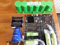
Hello,
Parts starts coming in and i expect the last parcel before the end of next week.
Without proper CAD/CAM software it is rather time consuming to '' redesign '' and also do the works in real life without have everything available. Most metal frame work inside the chassis is steel or aluminium and all ready have some holes that can be made bigger or threaded. ONCE the chassis is heavily populated bolts and nuts can be hard because you cannot reach both of them with a tool. I have lots of special tools to make threaded holes.
Doede ( DDDAC) made a short of redesign of his power supply so it will be a lot easier to use when there is limited space.
I will use one for the lifepo4 board and one for the Etherregen which will be attached to the outside of the DDDAC chassis.. The lifepo4 board will stay until i will find a way to use the supercaps with the lifepo4 cells.
Last week a company that collects old metal picked up some old big radiators at my house. He saw my pile of transformers and he told me he recently ran across a wooden crate filled with chokes made my Siemens. They have an instruction how to adjust the airgap. If i take them he doesnt have to take the copper and iron apart so it could be a win win situation.
Greetiings, eduard
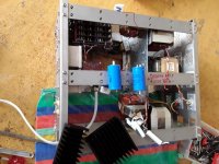
Attachments
- Home
- Source & Line
- Digital Line Level
- we need a tutorial