Hi MisterTwister
Re your rightmost illustration in Post#17.
For integrated reproduction I would suggest not 'subs', but light coned woofers or mid-bass...
Also a pair of inner back-of-waveguide edge side triangles from below the top driver to level with the lower ones, to create an inverted bipole BIB with the rear LF exiting from the top of the cabinet...
Cheers ............ Graham.
Construction suggestion: a scaffold/skeleton of plywood. like a boat hull.
a layer of ply over the top. plane edges to fit.
Are you thinking about 3 feet high?
a layer of ply over the top. plane edges to fit.
Are you thinking about 3 feet high?
Very smart. With the central placement in an 18" wide baffle you compensate the rise of a typical 8" fullrange driver between 500Hz and 2kHz, and with the loading you compensate the baffle loss between 200Hz and 300Hz.
another interesting looking waveguide can be seen here:
http://6moons.com/industryfeatures/rubanoide/rubanoide.html
i am looking forward to see more waveguided cone ob's .
i am very curious how it sounds .
http://6moons.com/industryfeatures/rubanoide/rubanoide.html
i am looking forward to see more waveguided cone ob's .
i am very curious how it sounds .
I've already started cutting and taping cardboard pieces. I hope first prototype box will be finished in a few days.
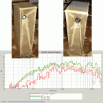
ok, here are first measurements. red curve is 3ft from baffle edge.
all others are taken from 8in distance. there is huge dip at 5khz, any ideas why it's there? 🙂 it flattens as you move farther away from speaker. and 12khz dip unfortunately remains there. Overall I'm very impressed, I think this design has potential. it sounds so natural and defenitely better than straight open baffle. I have few other drivers to try fe127, fr125 and neo8. especially I'm looking forward to neo8 test.
maybe I should have made waveguide on wide side of speaker.
Attachments
MisterTwister -
You're a Guy after my own heart! I love cardboard mock-ups! When I think an idea really might work I use OSB.
Hoping someone can help you with this and idea catches on. Simply must see someone attempt this concept with 6 and 8" FR's.
So many speakers, so little time.
Bluto

You're a Guy after my own heart! I love cardboard mock-ups! When I think an idea really might work I use OSB.
Hoping someone can help you with this and idea catches on. Simply must see someone attempt this concept with 6 and 8" FR's.
So many speakers, so little time.
Bluto
Graham Maynard, I was thinking about it too. But, if I make BIB, horn, or br on the back, speaker will loose that magical dipole sound.
I think it's better to build these without side walls.
It would make them look much smaller and non obstructive.
for example my 15in wide dipole speaker, seems much smaller than 9in wide floorstanding speaker. it even appears to be smaller and lighter than this cardboard box.
I think it's better to build these without side walls.
It would make them look much smaller and non obstructive.
for example my 15in wide dipole speaker, seems much smaller than 9in wide floorstanding speaker. it even appears to be smaller and lighter than this cardboard box.
Hi MisterTwister,
I assumed you intended to use the LF drivers connected for '+' to '+' bipole. If such LF drivers are then closed in there will be a greater system resonance peak than if the top is opened to relieve back pressure. An open top will not interfere with the main driver. Also with careful damping you will could gain useful LF augmentation around and below the 1/4 wave path difference length.
If running in '+' to '-' connected dipole there will be an odd sounding increasing LF cancellation with falling frequency, and this will negate fitting LF drivers at all.
Cheers ............. Graham.
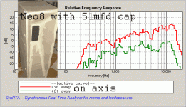
new neo8 measurement. I used 51mfd capacitor.
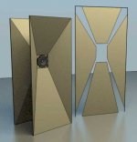
this waveguide is too small, I'm going to construct another one, for fr125. it will be approx 18in wide and 4ft tall. that's as far as size can go, for aestetical reasons. no sidewalls this time. just front and back baffle. I'll post 3d rendering next week.
this waveguide is too small, I'm going to construct another one, for fr125. it will be approx 18in wide and 4ft tall. that's as far as size can go, for aestetical reasons. no sidewalls this time. just front and back baffle. I'll post 3d rendering next week.
Attachments
Neat idea. For some reason I hear a TIE fighter when I look at these.

EEEEEEEEEEEEarrrrrrrrrrrrrrrrr
EEEEEEEEEEEEarrrrrrrrrrrrrrrrr
Hi Mister Twister
i would like to try something similar and was wondering if you could tell me how to calculate the cutout to get the angles for the waveguide right ?
and also some practical insight on how to best connect the waveguide to the baffle ?
its easier with cardboard but with wood of a certain thickness that is beyond my imagination and woodskills.
do you have any building process photos you can share??
malcolm
I had this idea about 2 years ago but never got around to doing anything with it. It's strange how you can think you've thought up something even remotely original when in fact you haven't.😱
When I first got the idea I quickly realized how impossible it would be for me to cut the complex angles with my limited tools. I decided that it would be "easier" to use stretched fabric and resin to create the guide.
Below is a pic of a very crude mock-up I just made in about 2 minutes to better show what I mean.
An externally hosted image should be here but it was not working when we last tested it.
Hey anonymus
that is a great idea . i might try that at some point .
now , where to get the resin ot what other material can be used to build the form ?
any sprayable plastic or something that isn't too toxic ?
how would one apply the resin on the fabric without changing the shape ?
malcolm
that is a great idea . i might try that at some point .
now , where to get the resin ot what other material can be used to build the form ?
any sprayable plastic or something that isn't too toxic ?
how would one apply the resin on the fabric without changing the shape ?
malcolm
you can use cad software to calculate cutout angles( I use 3dsmax).
I just detached sides of modeled enclosure and projected them on flat surface 2x4'(size of mdf sheet) ,see right side of the image.
I know, it's extremely difficult to make it out of thick mdf. That's why I'm using thin 1/8 in sheets.
I haven't started building yet. I'll post pictures when start making some progress.
I plan to use hot glue to hold pieces together, then add stronger wood glue.
This geometry should be quite ridgid,if not, I'll add ribs to the sides.
hum4god said:now , where to get the resin ot what other material can be used to build the form ?
any sprayable plastic or something that isn't too toxic ?
how would one apply the resin on the fabric without changing the shape ?
Ask a boat builder or custom car shop. They should know something. The car guys may know how to make it look good, too.
hum4god said:Hey anonymus
that is a great idea . i might try that at some point .
now , where to get the resin ot what other material can be used to build the form ?
any sprayable plastic or something that isn't too toxic ?
how would one apply the resin on the fabric without changing the shape ?
malcolm
I planned on using something like US Composites "B-440 Premium Polyester Layup Resin" over flannel or something similar. If the fabric is stretched tight enough and you use thin layers of resin the shape shouldn't deform (much). If you layer it evenly any sagging will be negligible.
I was just going to make a thin shell and then fill in the cavity will expanding foam or possibly sand if it could hold the weight. The guides would be formed on a MDF H-frame to which the driver would be firmly attached to the center baffle. This way the guide would not be structural and would only need not resonate.
many layers of thin ply.
cut a "pac-man's mouth" notch out of each sheet at a different place. About a 15-20 degree wedge should do it. pull the edges of the notch together to meet each other. Add a layer at a time, Perhaps use a vacuum bag to press it.
Trim the edges after it is complete.
cut a "pac-man's mouth" notch out of each sheet at a different place. About a 15-20 degree wedge should do it. pull the edges of the notch together to meet each other. Add a layer at a time, Perhaps use a vacuum bag to press it.
Trim the edges after it is complete.
- Status
- Not open for further replies.
- Home
- Loudspeakers
- Full Range
- waveguided open baffle