Do you think the other participants in that thread will get to the CAD part?
I'll ask them to go on with the thread - we intended to set up a step-by-step instruction on how to do a CAD drawing and import to ABEC anyway - and report back here as well...
BW,
Chris
References 1234
Some Links important to this Thread follow:
1) J. Panzer's AES BEM/LEM Paper
https://hal.archives-ouvertes.fr/hal-00811256/document
2) ABEC Horn Design Tutorial
http://www.randteam.de/_Docs/ABEC/Studies/Horn H 400 LE.pdf
3) D. Tengelsen's BYU Paper (CD Design)
http://scholarsarchive.byu.edu/cgi/viewcontent.cgi?article=3447&context=etd
4) P. Graham's Article (PP Overview)
WHG
Attachments
Last edited:
Use the 64 Bit version or a smaller number of threads and the problem is gone. 🙂
64 Bit sounds good
I'll ask them to go on with the thread - we intended to set up a step-by-step instruction on how to do a CAD drawing and import to ABEC anyway - and report back here as well...
BW,
Chris
Great work in the German DIY-Hifi-Forum. Very eager to know the right import method. Thank you Chris.
Some Links important to this Thread follow:
1) J. Panzer's AES BEM/LEM Paper
https://hal.archives-ouvertes.fr/hal-00811256/document
2) ABEC Horn Design Tutorial
http://www.randteam.de/_Docs/ABEC/Studies/Horn H 400 LE.pdf
3) D. Tengelsen's BYU Paper (CD Design)
http://scholarsarchive.byu.edu/cgi/viewcontent.cgi?article=3447&context=etd
4) P. Graham's Article (PP Overview)
WHG
Thank you for the links. Have been trying to get some good reading material on the design process.
Does anyone happen to know what depth the interface should have compared to the horn?My infinite baffle is at the mouth of the horn. From the help section I understand that interface is used to couple two subdomains. It can be used to simulate elements behind the infinite baffle. How far behind should it go? What is the importance of shape of the interface? The HORN 400 example also says that it can be used to avoid modeling the mouth exterior. I find this very confusing.
Last edited:
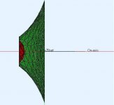
Well, I'm not entirely clear on the concept as well, i.e. the point I do not see is a rational for the depth (50mm) of the 'interface-box' in front of the finite baffle (=horn flange).
I simply varied the depth in the nodes script...
--to 5mm or 100mm and observed slightly different results for the directivity plot in VACS.
However, the general concept - a simplification in order to avoid modelling of the horn outside - is given in the solving script and seems quite clear to me:
May be more tomorrow...
BW, Christoph
I simply varied the depth in the nodes script...
Code:
  // Interface Baffle
  1350      0      170       0
  1351    250      170       0
  1352    250      170     -50
  1353      0      170     -50
  1354    250        0     -50
  1355    250        0       0
1356 0 0 -50However, the general concept - a simplification in order to avoid modelling of the horn outside - is given in the solving script and seems quite clear to me:
Code:
// In this example the radiation is from a finite baffle,
// which is formed by the horn-flange.
// Strickly we would have to model also the outside-walls
// of the horn. In order to avoid this, we can apply a simple
// trick.
// Assuming that some approximation is allowed, we can reduce the
// outside-walls of the horn to a simple wall on the rear
// of the horn-flange - note, as an approximation.
// This means SubDomain=2 is bounded by a simple rectangular box.
// Five sides of this box are formed by the interface.
// The rear-wall of this box is formed by following elements.
May be more tomorrow...
BW, Christoph
Interface
Ok. I understand the approximation now. However, I see changes in the directivity with change in depth just like you said. I also see changes in directivity with usage of different interface shapes. Do you think the interface has to have a similar shape to the horn mouth? The built-in SHELL shapes are not working well for me(Eg. Ellipse). They appear in the drawing but vanish during the meshing! The regular shapes work fine. I guess drawing the interface along with the horn is the best way to go about it (Though changing the depth each time is going to be a pain!).
Ok. I understand the approximation now. However, I see changes in the directivity with change in depth just like you said. I also see changes in directivity with usage of different interface shapes. Do you think the interface has to have a similar shape to the horn mouth? The built-in SHELL shapes are not working well for me(Eg. Ellipse). They appear in the drawing but vanish during the meshing! The regular shapes work fine. I guess drawing the interface along with the horn is the best way to go about it (Though changing the depth each time is going to be a pain!).
Sorry for being late here wildsteve. Due to lots of other commitments I haven´t been able to respond to anything for a while.
One hypothesis regarding the "off" radiation pattern at lower frequencies might be that when you use an infinite baffle setup ABEC doesn´t "see" the rear of the horn at all. In ABEC is´t perfectly possible to have a one-sided wall. I find this difficult to grasp myself, so sorry if my explanation/hypothesis is way off. If you were to make the horn itself "solid" where you make both the inside and the outside, the sound waves would wrap around at lower frequencies properly.
Another thing that could happen is leaks. I have not seen your model, but if your model has leaks between the subdomains it will cause strange effects - sometimes making ABEC use all the memory you have and stopping the solving.
I was also given a tip in my ABEC synergy horn thread http://www.diyaudio.com/forums/multi-way/267083-synergy-horn-3d-printing-entry-31.html about assigning damping factors to the various elements. Elements without damping factors in ABEC are assumed to be "rock hard and fully reflective", which tends to overestimate peaks and throughs, standing waves etc.
CAD imports to ABEC can be both easy and difficult. Easy: If you have a model which is solid one solid piece. Difficult: The opposite. I made a (not to scale, not realistic) dummy model of a paraline, and it was a lot of work assigning the different polygons the the correct subdomain and ensuring all the normals were correct.
In my synergy model I included a quadratic square throat to transition from the DE250 exit to the square synergy horn. If I meshed that too finely before importing, ABEC would override my settings for meshing, making the whole thing mesh at a too fine mesh size. MeshLab is a good tool to reduce mesh complexity before importing. 20k needs a very fine mesh size though, and unless you have a very high specced computer you´ll probably need to use symmetries. If your waveguide is symmetric (which I assume) you´ll save a lot by making your model of the waveguide, then chopping it so you have one quadrant before making a .mesh file and importing it to abec. If you also use meshlab to reduce the number of polygons it will make it even better. Of course, if you make it too coarse, it will have an acoustic effect...
Hope some of this helps. You can also post your model here and I can have a look. The whole synergy model is also posted in the thread mentioned above. Perhaps it can be useful, and more likely you´ll find improvement potential.. 🙂
Here´s the link for the paraline-sim: http://www.diyaudio.com/forums/multi-way/217298-square-pegs-87.html
Gaga - if it's ok with wildsteve would you mind posting the "Solving" and "Nodes" project files from the DIY HiFi Forum thread? I finally took the time to start working in ABEC and figured I'd follow your example there, however my drawing looks goofy when I add the interior box. I'd like to look at your example files and see where my error is. Thanks
Nevermind my last post to Gaga.......I figured it out. Some of the node coordinates had the xyz mixed up.
Yes, sure. As I did several versions, this one might be slightly different to the one shown in the ABEC-Thread. I have to check the files but just post this one as a start below.
I try to attach the project as .zip-file as well. However, file size was too big...
Hope this helps as a start. Feel free to ask for details. My replies might be a bit delayed, as I'm traveling actually...
BW,
Christoph
PS: Opps, just saw your post after sending my reply...
I try to attach the project as .zip-file as well. However, file size was too big...
Hope this helps as a start. Feel free to ask for details. My replies might be a bit delayed, as I'm traveling actually...
BW,
Christoph
PS: Opps, just saw your post after sending my reply...
Code:
//*****************************************************************************
//
// ABEC3 Nodes File
// Project: CP104 Enclosure 10
// Gaga 2015
//
//*****************************************************************************


// Symmetry-plane is yz (Sym=x)
// Front in xy-plane pointing along z-axis
// Height is 297mm  (in y)
// Width is  74mm  (in x)
// Depth is  200mm  (in -z)


Nodes "N1"

Scale=1mm

// Node #, x, y, z

2001	74 297   0
2002	 0 297   0
2003	 0 0     0
2004	74 0     0
2201	74 297 -200
2202	 0 297 -200
2203	 0 0   -200
2204	74 0   -200


// Enclosure inside 12mm

4001	62 285   -12
4002	 0 285   -12
4003	 0  12   -12
4004	62  12   -12
4201	62 285  -188
4202	 0 285  -188
4203	 0  12  -188
4204	62  12  -188


//  Diaphragm front side
  3000  0.0      92.0       0  // Center diaphragm
  3001  0.0      92.0      43.5
  3002  0.0     135.5       0
Code:
//*****************************************************************************
//
// ABEC3 Enclosure File
// Project: CP104 Enclosure 21
// Gaga 2015
//
//*****************************************************************************


File="Nodes CP104 21.txt"


Subdomain_Properties "Interior"
  Subdomain=1
  ElType=Interior
  Color=Green 0.7

SubDomain_Properties 'Vent'
    SubDomain=2
    ElType=Interior

Subdomain_Properties "Exterior"
  Subdomain=3
  ElType=Exterior

//Infinite_Baffle
//  Subdomain=3
//  IBPlane=x;  IBOffset=0m  // Floor Reflektion


// Gehäuse-Elemente
Elements "Enclosure-Interior"
  RefNodes="N1"
  SubDomain=1

  101   4004  4204  4203  4003  // bottom wall
  102   4204  4201  4202  4203  // rear wall
  103   4202  4201  4001  4002  // top wall
  104   4001  4201  4204  4004  // side wall

Elements "Enclosure-Exterior"
  RefNodes="N1"
  SubDomain=3

  101   2003  2203  2204  2004  // bottom wall
  102   2203  2202  2201  2204  // rear wall
  103   2002  2001  2201  2202  // top wall
  104   2004  2204  2201  2001  // side wall


// Innenseite BR-Rohr - = Subdomäne 2
  Duct "Vent-Inner"
  SubDomain=2
  EdgeLength=10mm
  DuctType=Circle
  dD=25mm
  Len=100mm

// BR-Rohr Außenseite - gehört zur Gehäuße-Innenseite (Subdomain 1)
  Duct "Vent-Outer"
  SubDomain=1
  EdgeLength=10mm
  DuctType=Circle
  dD=26mm
  Len=100mm
  SwapNormals
  t1=0mm


// Verbindung BR-Rohr Innen- und Außenseite - Subdomäne 1
Transition "Vent-Flange"
  Subdomain=1
  EdgeLength=5mm
  RefElements="Vent-Inner","Vent-Outer"
  RefEdges=2,2


// Verbindungsfläche BR-Rohr - Gehäuße
Transition "I-Vent-Inner"
  Subdomain=2,1
  EdgeLength=10mm
  RefElement="Vent-Inner"
  RefEdge=2

// Verbindungsfläche BR-Rohr - Außen
Transition "I-Vent-Outer"
  Subdomain=2,3
  EdgeLength=10mm
  RefElement="Vent-Inner"
  RefEdge=1


WallImpedance "Vent Damping"
  RefElements="Vent-Inner"
  ImpType=Damping
  Value=0.1

WallImpedance "Enclosure Damping"
  RefElements="Enclosure-Interior"
  ImpType=Damping
  Value=0.01


//Fronteite Gehäuse - Frontplatte
Baffle 'Exterior'
  Subdomain=3
  EdgeLength=25mm, 25mm
  Vertices=2003,2004,2001,2002  "N1"
  101  Ref="Cone Front"       x=0mm  y=92mm
  102  Ref="Cone Rear"        x=0mm  y=92mm
  103  Ref="Vent-Inner"       x=0mm  y=200mm
  104  Ref="Vent-Outer"       x=0mm  y=200mm


//Innenseite Frontplatte
Baffle "Interior"
  Subdomain=1
  EdgeLength=25mm, 25mm
  SwapNormals=true
  Vertices=4003,4004,4001,4002 "N1"


Diaphragm  "Cone Front"
  Side=Front                   	// Membran Vorderseite
  DrvGroup=1001                	// Driving group - Link zum Antrieb
  SubDomain=3                  	// Definition Sub-Domäne 1 = Außen
  EdgeLength=6mm		// Kontrolliert Feinheit des meshings

  dD=87mm                     	// Diameter of cone
  tD1=15mm                     	// Inner depth of cone to base of dust cap
  dD1=-1mm                    	// Diameter of dust cap
  hD1=1mm                     	// Height of dust cap
  Simple=true               	// Simple model Simple=true following parameters ignored
  Ws=2mm                    	// Width of outer suspension
  hD2=15mm                    	// Height of total cone on the outside
  dVC=20mm                     	// Diameter of voice coil
  hVC=5mm                      	// Height of voice coil
  dM=65mm                     	// Diameter of magnet
  hM=35mm                      	// Height of magnet

Diaphragm  "Cone Rear"
  Side=Rear                    // Membran Rückseite
  DrvGroup=1002                // Driving group - Link zum Antrieb
  SubDomain=1                  // Definition Sub-Domäne 1 = Gehäuße innen
  RefDiaphragm="Cone Front"    // Bezug auf die Membran-Vorderseite "Cone front"
  t1=-12mm    		       // Offset bezogen auf Baffle-Rückseite
Last edited:
PWT
WS,
I have not read this entire thread, but use of a Plane Wave Tube is the standard practice for measuring compression driver performance.
Here are some PWT references:
AES Standards News Blog AES-1id-2012, Plane-wave tubes - Design and practice
WHG
WS,
I have not read this entire thread, but use of a Plane Wave Tube is the standard practice for measuring compression driver performance.
Here are some PWT references:
AES Standards News Blog AES-1id-2012, Plane-wave tubes - Design and practice
WHG
Attachments
Last edited:
Problem solved (Almost!)
Excellent tips! Doing away with the infinite baffle resolved most of the directivity issues at low frequencies. I was also using a box-interface. It is not required in my case as the rear need not be modeled. Changed it to a flat one. However, I am still struggling with a low-spec computer! Hope I can let you know the results soon.
Sorry for being late here wildsteve. Due to lots of other commitments I haven´t been able to respond to anything for a while.
One hypothesis regarding the "off" radiation pattern at lower frequencies might be that when you use an infinite baffle setup ABEC doesn´t "see" the rear of the horn at all. In ABEC is´t perfectly possible to have a one-sided wall. I find this difficult to grasp myself, so sorry if my explanation/hypothesis is way off. If you were to make the horn itself "solid" where you make both the inside and the outside, the sound waves would wrap around at lower frequencies properly.
Another thing that could happen is leaks. I have not seen your model, but if your model has leaks between the subdomains it will cause strange effects - sometimes making ABEC use all the memory you have and stopping the solving.
I was also given a tip in my ABEC synergy horn thread http://www.diyaudio.com/forums/multi-way/267083-synergy-horn-3d-printing-entry-31.html about assigning damping factors to the various elements. Elements without damping factors in ABEC are assumed to be "rock hard and fully reflective", which tends to overestimate peaks and throughs, standing waves etc.
CAD imports to ABEC can be both easy and difficult. Easy: If you have a model which is solid one solid piece. Difficult: The opposite. I made a (not to scale, not realistic) dummy model of a paraline, and it was a lot of work assigning the different polygons the the correct subdomain and ensuring all the normals were correct.
In my synergy model I included a quadratic square throat to transition from the DE250 exit to the square synergy horn. If I meshed that too finely before importing, ABEC would override my settings for meshing, making the whole thing mesh at a too fine mesh size. MeshLab is a good tool to reduce mesh complexity before importing. 20k needs a very fine mesh size though, and unless you have a very high specced computer you´ll probably need to use symmetries. If your waveguide is symmetric (which I assume) you´ll save a lot by making your model of the waveguide, then chopping it so you have one quadrant before making a .mesh file and importing it to abec. If you also use meshlab to reduce the number of polygons it will make it even better. Of course, if you make it too coarse, it will have an acoustic effect...
Hope some of this helps. You can also post your model here and I can have a look. The whole synergy model is also posted in the thread mentioned above. Perhaps it can be useful, and more likely you´ll find improvement potential.. 🙂
Here´s the link for the paraline-sim: http://www.diyaudio.com/forums/multi-way/217298-square-pegs-87.html
Excellent tips! Doing away with the infinite baffle resolved most of the directivity issues at low frequencies. I was also using a box-interface. It is not required in my case as the rear need not be modeled. Changed it to a flat one. However, I am still struggling with a low-spec computer! Hope I can let you know the results soon.
Hi,
This is just to let you know that there is a step-by-step description on how to go from a CAD-drawing to a mesh and then import into an ABEC-script available now within the ABEC-thread in the German DIY-Hifi-Forum.
If interested have a look here... Still in German, but may be helpful anyway.
Any news about your modeling, wildsteve?
BW,
Christoph
Update
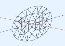
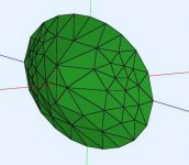
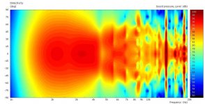
Hi all. With all of your help I have been able to run simulations of a waveguide. I have not used an infinite baffle. Instead, I followed Cookiemonster's suggestion to model the rear. To make it simple(because I am lazy), I closed the rear with a simple cover(shown in 4th attachment). I have used a filter frequency of 1800Hz for the tweeter. I should be getting fairly constant directivity(+/- 60 degrees) starting right from 2000Hz upto 10KHz but as you can see, the plot shows otherwise. I also found that changing the meshing frequency in ABEC greatly changes the directivity pattern. Is this because I have meshed parts using different mesh-sizes?
Most of you might be knowing how to translate websites but in case anyone wants to read Gaga's thread in English: Google Translate
The thread also explains how to group many elements together during the meshing stage.It will help me A LOT! A tip: Direction of normals can be inverted by using a negative sign for the respective surface while assigning physical groups.If you are using gmsh, It can be done in 'edit file' under geometry.
Attachments

Last edited:
Wow - very nice!
Just curious - which CAD-software did you use to model the waveguide? How did you construct the oval shape of the waveguide?
Christoph
Just curious - which CAD-software did you use to model the waveguide? How did you construct the oval shape of the waveguide?
Christoph
I used FreeCad to model the waveguide. I drew 30 ellipses(each with a slight increment in height and size) in the PartDesign workbench. Then I made a loft using all of them. Also check out this thread on 3D modeling: http://www.diyaudio.com/forums/multi-way/279476-3d-modeling-tips-tricks.html
Last edited:
Is that the shape of the enclosure you are going to use? The sharp lip will introduce significant diffraction effects.I have not used an infinite baffle. Instead, I followed Cookiemonster's suggestion to model the rear. To make it simple(because I am lazy), I closed the rear with a simple cover(shown in 4th attachment).
It means you have not used enough elements for the solution to approach "grid independence" where adding more elements will not significantly change the solution. The minimum number of elements to achieve this is often quoted as a number of elements per wavelength. Alternatively you can find it yourself by performing a sequence of simulations of the same problem with progressively finer grids and looking for when the solution stops changing.I also found that changing the meshing frequency in ABEC greatly changes the directivity pattern. Is this because I have meshed parts using different mesh-sizes?
Is that the shape of the enclosure you are going to use? The sharp lip will introduce significant diffraction effects.
It means you have not used enough elements for the solution to approach "grid independence" where adding more elements will not significantly change the solution. The minimum number of elements to achieve this is often quoted as a number of elements per wavelength. Alternatively you can find it yourself by performing a sequence of simulations of the same problem with progressively finer grids and looking for when the solution stops changing.
Actually no. I am planning on using a rectangular box for the enclosure. I wish to simulate only the waveguide's directivity at the moment. The reason why I chose to use such a simple enclosure for the simulation was to reduce the computation time. My idea was to assign the enclosure with a very high damping value. Despite using a high damping value, I still get diffraction effects as you said. So I am back to using the box enclosure again but this time with a smoother transition to the waveguide. I see a better response now. Thank you for pointing that out.
I understand the concept of "grid independence" but since I have to mesh the geometry once before importing(in gmsh) and once after(in ABEC), I am trying to find a balanced meshing method. ABEC suggests on using coarse mesh in gmsh but doing so affects the high frequency response.
Last edited:
- Status
- Not open for further replies.
- Home
- Loudspeakers
- Multi-Way
- Waveguide model