Maybe a practical example of how I correct my arrays can help,
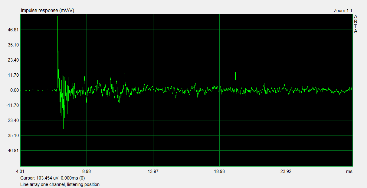
Impulse & STEP response Line Array, 25 drivers 85.5 mm c.t.c. spacing:

* some minor Pré EQ has been applied to get the signal within the DRC-FIR correction limits
Based on this RAW impulse I let DRC-FIR calculate it's correction. The actual correction is based on a sliding window gating of the impulse. I've experimented with the sliding window settings to get optimum (for me anyway) results.
The calculated correction (for a flat target):

Longer window settings would theoretically correct more of the impulse. I.m.h.o. this has a bigger effect at the sweet spot but gets less ideal fast when you move outside of this sweet spot. The correction window used here is 6 cycles at 20 Hz, tapering down to about 4 cycles around 2000 Hz and up again to 9 cycles at 20000 Hz.
Resulting impulse response after convolving with the correction:

Frequency response and phase gated 4 cycles in REW:

Ungated response smoothed 1/12:

I've plotted the calculated minimum phase to compare. The template I used for this correction is largely minimum phase, but with an excess phase correction window from 20 Hz to 500 Hz. 3 cycles at 200 Hz tapering to 2.3 cycles at 500 Hz. The idea here is to not correct the room too much (you see the room induced dip at ~73 Hz) but still correct the early wave front.
I've studied all plots to see which parts I wanted to correct and which parts happen later in time and should be left alone.
Here's the same 4 cycles gated window of the first impulse I showed (the RAW response):

And it's ungated window, smoothed 1/12.

Hope this helps.
P.S.
Keyser, see your raw impulse and mine. Agreeable for the most part but it is obvious you have a lot of strong early reflections (not the first 0.6 ms, that's the time smeared pulse you are looking for) in that room after the main pulse. Those will have a strong effect on the total sound you hear.
Impulse & STEP response Line Array, 25 drivers 85.5 mm c.t.c. spacing:
* some minor Pré EQ has been applied to get the signal within the DRC-FIR correction limits
Based on this RAW impulse I let DRC-FIR calculate it's correction. The actual correction is based on a sliding window gating of the impulse. I've experimented with the sliding window settings to get optimum (for me anyway) results.
The calculated correction (for a flat target):
Longer window settings would theoretically correct more of the impulse. I.m.h.o. this has a bigger effect at the sweet spot but gets less ideal fast when you move outside of this sweet spot. The correction window used here is 6 cycles at 20 Hz, tapering down to about 4 cycles around 2000 Hz and up again to 9 cycles at 20000 Hz.
Resulting impulse response after convolving with the correction:
Frequency response and phase gated 4 cycles in REW:
Ungated response smoothed 1/12:
I've plotted the calculated minimum phase to compare. The template I used for this correction is largely minimum phase, but with an excess phase correction window from 20 Hz to 500 Hz. 3 cycles at 200 Hz tapering to 2.3 cycles at 500 Hz. The idea here is to not correct the room too much (you see the room induced dip at ~73 Hz) but still correct the early wave front.
I've studied all plots to see which parts I wanted to correct and which parts happen later in time and should be left alone.
Here's the same 4 cycles gated window of the first impulse I showed (the RAW response):
And it's ungated window, smoothed 1/12.
Hope this helps.
P.S.
Keyser, see your raw impulse and mine. Agreeable for the most part but it is obvious you have a lot of strong early reflections (not the first 0.6 ms, that's the time smeared pulse you are looking for) in that room after the main pulse. Those will have a strong effect on the total sound you hear.
I'm assuming the smeared impulse response of my line-arrays is caused by real-world limitations such as non-infinitesimal driver spacing and a not perfectly reflecting floor and ceiling. Do you agree?
Yes, the fact that your impulse response looks like multiple discrete impulses rather than a smooth decay is almost certainly because of the inter-driver spacing. In my simulation, this also causes a ripple in frequency, which of course can't be fixed with a simple high pass filter.
The rise and fall of energy is likely related to room reflections, perhaps from side walls?
I am curious at what distance you made measurements.
Last edited:
measurement distance
It would be interesting to know the measurement distance. The other thing I wonder about is the floor and ceiling reflections and what effect any imbalance or discontinuity in these reflections might have. If you take first reflections into account I think the "far" drivers lag by more than 4ms.
It would be interesting to know the measurement distance. The other thing I wonder about is the floor and ceiling reflections and what effect any imbalance or discontinuity in these reflections might have. If you take first reflections into account I think the "far" drivers lag by more than 4ms.
Care to explain how you reach that figure? 4 ms would relate to about 1.37 meter difference in distance to the mic.
I don't see that in this STEP:

Nor in this impulse:
Knowing my own distance I'd guess about ~ 3 meter distance to listening position? Last firing driver is no more than about ~0.6-0.8 ms behind the main pulse in my eyes. After that I only seem to detect (early) reflections. Judging by the STEP here, the impulse has a different time line not corresponding to this STEP. It would be easier to judge in an impulse and STEP that belong together.
Seeing the impulse still makes me curious about a single driver impulse from one of the drivers used in this array.
I don't see that in this STEP:
Nor in this impulse:
Knowing my own distance I'd guess about ~ 3 meter distance to listening position? Last firing driver is no more than about ~0.6-0.8 ms behind the main pulse in my eyes. After that I only seem to detect (early) reflections. Judging by the STEP here, the impulse has a different time line not corresponding to this STEP. It would be easier to judge in an impulse and STEP that belong together.
Seeing the impulse still makes me curious about a single driver impulse from one of the drivers used in this array.
Last edited:
bbutterfield, my own floor-to-ceiling array constitutes of thirty 3" full-range drivers. I've EQ'ed it as best I can, but the step response nevertheless is similar to the one you posted earlier.
.
keyser, how are you implementing the High Pass Filter?
Here's some research that might help answer some questions.
Can Line Arrays Form Cylindrical Waves? A Line Array Theory Q & A
Can Line Arrays Form Cylindrical Waves? A Line Array Theory Q & A
Sorry to resurrect an old thread but I'm working on a line source and want to be sure I have my facts straight as I interpret my measurement results.
Am I correct when concluding that different listening positions will have different uncorrected impulse responses because the arrival time differences will be different? And further, that different equalization will be necessary for different listening distances if the goal is to flatten the magnitude response and simultaneously clean up the impulse response?
Or to put it more succinctly, you can only equalize the line source to give a clean impulse and flat frequency response for one listening distance at a time. Is that correct?
Thanks,
Few
- Status
- Not open for further replies.
- Home
- Loudspeakers
- Multi-Way
- Wave-front shape and impulse response: spherical, cylindrical, plane-wave