Just to be sure
Pfff... i made some calculations.
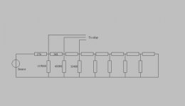
The Pass P1.7 uses : Output_Line -> R1 - Out - R2 - Gnd.
8 relays swith 8 resistors parallel to R1 or R2 to create 254 different attenuator values from -48dB to -0.03dB.
Two steps are not allowed : 00000000 and 11111111.
Can someone confirm these findings and tell me if the -48dB step is enough for a close to mute setting ?
In Jens' volume control : does it switch different resistor combinations in every step ? Or does he also switch resistors parallel to another ???
until i'm sure that i understand these digital volume controllers i'll stay with two potties
Grtz
Nick
Pfff... i made some calculations.
The Pass P1.7 uses : Output_Line -> R1 - Out - R2 - Gnd.
8 relays swith 8 resistors parallel to R1 or R2 to create 254 different attenuator values from -48dB to -0.03dB.
Two steps are not allowed : 00000000 and 11111111.
Can someone confirm these findings and tell me if the -48dB step is enough for a close to mute setting ?
In Jens' volume control : does it switch different resistor combinations in every step ? Or does he also switch resistors parallel to another ???
until i'm sure that i understand these digital volume controllers i'll stay with two potties
Grtz
Nick
I'm not exactly sure what Jens design does, but I think its pretty much what you described though. All I can say is that I was using dual potties 😱 too and the difference was remarkable.....other than adding the Aleph 2's to my system it by far made the 2nd biggest improvement in my system. I say go ahead and build it and worry about how it works later on........
Mark
Mark
Mark A. Gulbrandsen said:I'm not exactly sure what Jens design does, but I think its pretty much what you described though. All I can say is that I was using dual potties 😱 too and the difference was remarkable.....other than adding the Aleph 2's to my system it by far made the 2nd biggest improvement in my system. I say go ahead and build it and worry about how it works later on........
Mark
Mark,
did you build the Pass configuration or the Jens device ???
Grz
Nick
Could you post or mail me the schematic of this volume control ?
I haven't found it yet. (or overlooked it )
)
Grtz
Nick
I haven't found it yet. (or overlooked it
)Grtz
Nick
Nick,
Just to clarify, my 8-bit counter starts at 00000000 (mute) and stops at 11111111, which are 256 steps. If you use the Aleph P1.7 ladder configuration, you will have a level control of about 48dB. My Aleph P1.7 clone has NP’s ladder configuration, and it works fine. In my BZLS I use the same 8-bit counter, but instead of a ladder configuration voltage divider of -40dB, -20dB, -10dB..., which allows for a volume control of about 80dB.
Jens

Nick,
Regarding the ladder configuration, have a look to the Aleph P1.7 schematic. In case of the voltage divider configuration in my BZLS, see appended file. As you can see, voltage dividers are completely out of the volume control (via relays) so long as they are not needed.
Jens
Regarding the ladder configuration, have a look to the Aleph P1.7 schematic. In case of the voltage divider configuration in my BZLS, see appended file. As you can see, voltage dividers are completely out of the volume control (via relays) so long as they are not needed.
Jens
Attachments
APOX
Hi,
Please don't be mad at me, I'm not trying to steal your thread.
But, I just wanted to throw in an option.
We recently completed a relay controlled volume controller board.
in fact, we now have 3 different versions with a remote control LCD interface and a relay controlled input select board.
We are selling this as a kit
The APOX Kit
There is a long thread going in the trading post, if you want to read about it.
Thanks,
Craig Beiferman
So Craig....
If I bought one of these kits would the readout say APOX or is that something done just for the photos???
Mark
If I bought one of these kits would the readout say APOX or is that something done just for the photos???
Mark
From the DipChip site:
3) Display Text for Inputs/Splash
So my guess is that it the display would say "Mark A. Gulbrandsen" which would likely fit too ....
Petter
3) Display Text for Inputs/Splash
So my guess is that it the display would say "Mark A. Gulbrandsen" which would likely fit too ....
Petter
Mark,
The splash screen is customizable via the encoder interace.
You just dial in the characters you want, and the results are stored permanently in EEPROM.
You can also customize the names for the input selection channels.
Mark's CD player
Super Tuner
etc..
Thanks,
Craig Beiferman
The splash screen is customizable via the encoder interace.
You just dial in the characters you want, and the results are stored permanently in EEPROM.
You can also customize the names for the input selection channels.
Mark's CD player
Super Tuner
etc..
Thanks,
Craig Beiferman
I have a my board finished here, maybe a few people are interested to see how it looks.
http://www.diyaudio.com/forums/showthread.php?postid=348773#post348773
http://www.diyaudio.com/forums/showthread.php?postid=348773#post348773
Jen:
In response to your Post #52 and before, I have your schematic for the 8-bit control board. Can you share the relay board design shown in the Post #52 that you are using in your BZLS?
I made my ADC0804 using 6-bit, but not quite satisfy. I would like to move on to a better solution one.
Thanks,
Thomas
- Status
- Not open for further replies.
- Home
- Amplifiers
- Pass Labs
- Wanted : design PCB for relay controlled volume