Sorry messed up yesterday 337 is negative voltage adjustable regulator I confused it with 317.
Usually these regulators 780x, 790x, 31x drop around 1.2 volts this means that if you want an output voltage of 7805 you need to have an input voltage of 6.2-6.5 at the input terminals.
By looking at your previous responses it seems that there is an issue of input voltages as far as two regulators are concerned, 7905 -2.4 the input voltage is 3.5 so its dropping it by 1.1 you should have atleast 6.2 at the input to get negative 5 volts.
as per data sheet of AD1864 you should have +5 to +12 volts at Pin 1, -5 to -12 at pin 24 (analog supply), same with digital supply at pin 9 and 16 of AD1864.
Last edited:
Pin 1 to pin 2 measures same as pin. 3 to pin 2 about 6R No value from pin 2 to pin 4 and 6
It seems that the left secondary winding of the transformer is indeed center tapped.
My suggestion is to use the 15vx2 toroid connect to pins 1, 2 and 3 and use another 15VAC or DC source to power pins 4 and 6 on the PCB.
Last edited:

Sorry, I edited my post #24 while you were replying.
My suggestion is to use a 15vx2 toroid connected to pins 1, 2 and 3 and make sure it's phased correctly.
And use another 15VAC or DC power source (another transformer or bench power supply) to power pins 4 and 6 on the PCB.
If everything works fine, then look for a new transformer.
My suggestion is to use a 15vx2 toroid connected to pins 1, 2 and 3 and make sure it's phased correctly.
And use another 15VAC or DC power source (another transformer or bench power supply) to power pins 4 and 6 on the PCB.
If everything works fine, then look for a new transformer.
I was thinking the same. I can squeeze in a second toroidal in there to provide the 2 other connections.
Wouldn't that be a 15-0-15 where a 7.5-0-7.5 is appropriate?Sorry, I edited my post #24 while you were replying.
My suggestion is to use a 15vx2 toroid connected to pins 1, 2 and 3 and make sure it's phased correctly.
And use another 15VAC or DC power source (another transformer or bench power supply) to power pins 4 and 6 on the PCB.
If everything works fine, then look for a new transformer.
(7.5x1.414)-1.4=9.2 volts for 7810 you need atleast 11.5 volts to get 10 volts
(12x1.414)-1.4=15.568 Volts
(15x1.414)-1.4=19.81 Volts
I'd rather go for a 12+12 and 9 volts trafo
(12x1.414)-1.4=15.568 Volts
(15x1.414)-1.4=19.81 Volts
I'd rather go for a 12+12 and 9 volts trafo
No quote button on your post rehanabid? I have not seen a post I can't reply to before.
There is a second secondary winding, that doesn't use a center tap. It supplies a diode bridge, who's negative output is tied to the center tap of the first. I thought that could be for the 10v. I'm flying blind with just one pic to look at, so I can't move forward at this point. I feel like I have a satnav, but no map. I'm going to get lost 🙂
There is a second secondary winding, that doesn't use a center tap. It supplies a diode bridge, who's negative output is tied to the center tap of the first. I thought that could be for the 10v. I'm flying blind with just one pic to look at, so I can't move forward at this point. I feel like I have a satnav, but no map. I'm going to get lost 🙂
It is probably a bug in the php, the last available post on any thread, there is no quote button as compared to any other post, so one has to manually select the last post and right click and then select quote. 😉No quote button on your post rehanabid? I have not seen a post I can't reply to before.
There is a second secondary winding, that doesn't use a center tap. It supplies a diode bridge, who's negative output is tied to the center tap of the first. I thought that could be for the 10v. I'm flying blind with just one pic to look at, so I can't move forward at this point. I feel like I have a satnav, but no map. I'm going to get lost 🙂
Thats why I'd rather choose a 12-0-12 volt secondary and a 9-0 volt secondary trafo, tried to look for the service manual of the DAC but couldn't find it.
Basically just educated guess based upon data sheet of AD1864 and just top layer of PCB.
That's it... last post 🙂
Another Wadia from the same decade, might offer some clues. It used the same iec switching box, but otherwise not a lot in common.
Another Wadia from the same decade, might offer some clues. It used the same iec switching box, but otherwise not a lot in common.
It's all very close really. The guy (from here) put in a new transformer a couple of volts higher. It ran warm, but no issue. I would still like to see more though.Wadia X-32 secondaries are;
Brown/Green/Brown - dual 10.2v AC windings
Red/Yellow/Red - dual 12.4v AC windings
This is loaded, provides 12 and 15v DC rails - then lots of other regulators all over the PCB
Last edited:
Just a hint as I made a rudimentary datasheet for these and maybe they will fit in your Wadia. I also designed 65 x 90 mm breakout boards with onboard fuse, screw connectors, mounting holes etc. One silent (custom wound) 10VA Talema toroid with 4 output voltages which is both very old fashioned and very welcome:
https://www.ebay.de/itm/384519259262?chn=ps&_ul=DE&_trkparms=ispr=1&amdata=enc:1OR7Tm8zoQgK_747zT7nrvw6&norover=1&mkevt=1&mkrid=707-168914-933862-8&mkcid=2&itemid=384519259262&targetid=325425753764&device=c&mktype=pla&googleloc=9044159&poi=1010605&campaignid=20354632509&mkgroupid=154875659727&rlsatarget=pla-325425753764&abcId=&merchantid=7364532&gad_source=1&gclid=EAIaIQobChMIiv-wsfS8hwMVdZKDBx0NERQ4EAQYASABEgLeVfD_BwE
1. Please note that the voltages were measured without any load. Both 18V windings measure 15V under full load.
2. Pinout is also custom due to the original customers design criteria and 4 windings!
3. Classic/old 78xx, 79xx, LM317/337 should be used with 3V dropout voltage in mind. It depends on the output current but it is wise to calculate worst case. Recently produced versions often function OK with just above 2V dropout at full output current I noticed.
4. If the 7805 is too tight (what is the load current?) with 5..6 V AC then Schottky rectifiers and the NCV7805 could be a solution (2V dropout).
Last edited:
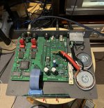
Some progress!
I have installed the 2 transformers
One 15-0-15 with the center tap connected to pin 2 and another same one using center tap to pin 4 and 15v to pin 6
Getting all correct voltages on the regulators
337 output 10v
7810 ….10v
7805…. 5v
7905….. -5v
I let it run for a couple of hours and regulators got barely warm
Connected to the rest of the system and sweet music is flowing again 👍
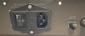
Also Installed a new input filter with a switch for 240v only.
Thank you to everyone chiming in for your help. Much appreciated
I have installed the 2 transformers
One 15-0-15 with the center tap connected to pin 2 and another same one using center tap to pin 4 and 15v to pin 6
Getting all correct voltages on the regulators
337 output 10v
7810 ….10v
7805…. 5v
7905….. -5v
I let it run for a couple of hours and regulators got barely warm
Connected to the rest of the system and sweet music is flowing again 👍
Also Installed a new input filter with a switch for 240v only.
Thank you to everyone chiming in for your help. Much appreciated
Attachments
Just make sure you measure ripple voltages and check if the filter caps and the regulators are not running against limits with regards to maximum (input) voltage and for the regulators dropout voltage (in Volts so V) and dissipation. So input voltages should be checked too, especially of the 7805/7905.
It would have been better to use solder pins for the AC wiring to the board as the pads possibly peel off when mechanical force is applied. Replace the blue electrolytic cap for one that fits on the PCB.
* Overdimensioning the filter caps with higher working voltage and higher allowable temp never hurts, value can be a bit larger too when modern versions have the same footprint.
My hunch is that one of the transformers should have lower secondary voltages but I don't have a schematic.
Last edited:
Tony at Coherent Audio in the uk is a Collector of all things vintage Wadia. He has a good size collection of early Wadia dacs, 30-40 units, well worth dropping him a line.
I installed pins on the board 👍It would have been better to use solder pins for the AC wiring to the board as the pads possibly peel off when mechanical force is applied. Replace the blue electrolytic cap for one that fits on the PCB
The height of the caps is an issue, Nichicon KG and KA for audio is what I used. If I find something suitable for the blue one I will.
The DAC sounds great. I also have a Sony R2R ( DAS-R1) and the Wadia is such a great value comparing with it.
Also upgraded the OPA606KP with Burson audio V6 vivid.
Some measurementsJust make sure you measure ripple voltages and check if the filter caps and the regulators are not running against limits with regards to maximum (input) voltage and for the regulators dropout voltage (in Volts so V) and dissipation. So input voltages should be checked too, especially of the 7805/7905.
It would have been better to use solder pins for the AC wiring to the board as the pads possibly peel off when mechanical force is applied. Replace the blue electrolytic cap for one that fits on the PCB.
* Overdimensioning the filter caps with higher working voltage and higher allowable temp never hurts, value can be a bit larger too when modern versions have the same footprint.
My hunch is that one of the transformers should have lower secondary voltages but I don't have a schematic.
337 input -20v
7810 input 21v
7805 input 20v
7905 input -21v
I don’t see any AC voltage present on the outputs of the regulators.
Played all day yesterday and the regulators were just warm to the touch.
Still too high voltages. Warm to the touch because of old fashioned overdimensioned large area heatsinking.
7805 with only 250 mA load: (20-5)/0.25=3.75W
No AC at the outputs is good 🙂 Normally ripple voltage is measured at the inputs of regulators.
7805 with only 250 mA load: (20-5)/0.25=3.75W
No AC at the outputs is good 🙂 Normally ripple voltage is measured at the inputs of regulators.
Last edited:
Yes, the whole case is a heatsink.Still too high voltages. Warm to the touch because of old fashioned overdimensioned large area heatsinking.
7805 with only 250 mA load: (20-5)/0.25=3.75W
Choice: let I convert valuable energy to useless heat without any reason or do I design for lower losses/higher efficiency/higher reliability?
If the choice is accepted as a challenge or personal contest in electric elegancy then (re)designing can be fun.
If the choice is accepted as a challenge or personal contest in electric elegancy then (re)designing can be fun.
Last edited:
- Home
- Source & Line
- Digital Source
- WADIA 12 dead transformer