
I agree with it is fun Sometimes measurements are fun. I didn't have to do pulsed RF, just relatively low frequency RF for calibrating.
Back 1960's you saw tubes , transistors and chips all same time. Today almost everything has chip with few transistor.
Most clock radios use chip that was designed in 1970's. They still use the IF transformer/Can and needs to adjust.
FYI Most radios today the problems with the adjustable resistor for volume or a switch.
The chip just keeps going.
Dave
Hi Dave,
Yes, my early career had me learning and working on a mix of tubes and solid state. Germanium transistors taught me a lot about semiconductors.
I was apprenticed by older service guys who knew tubes. They even trained me how to properly clean controls (you don't load them up with cleaner!). Also how to take in clues from all around the circuit and chassis. Most importantly, what the customer can tell you they don't even know is important. That goes for commercial - industrial customers as well.
All this knowledge is applied to solid state, and especially calibration of test equipment and industrial controls. History and environment is so important!
I try not to look at lifestyle equipment. Good friends rope me into that stuff. Clock radios? Nightmares from early days as a tech, but I know how to service all kinds of stuff I won't touch today. Yes, fixing some parts as well because you can't buy them today. Who does that? Yes, those clock radio chips tend to keep going, power supplies and everything else fails. I love it if a chip dies, easy "no, sorry it can't be fixed". When friends or family has something like this, it's always "an easy fix". Never mind it can take a long time to actually fix it right. That's after gluing old plastic back together and all the other horrors time aflects equipment with.
When I was at Rockwell/Collins now part of RTX doing MOPS (Minimum Operational Performance Standards)
on a product all the test equipment and cables were specified and the original test equipment and
cables had to be used to evaluate new versions of the equipment. Traceability.
Usually on tube amplifiers the voltage measurements are stated for a tube VTVM on the schematic
or service manual.
Therefore a FET VM will probably not give you the same readings as when your amp was made.
Last edited:
Hi RJM1,
Actually, assuming the input impedance is the same, it should give exactly the same readings. I had converted several Heathkit VTVMs to solid state FET input types. The movement is still average responding, so there is no difference at all.
Actually, assuming the input impedance is the same, it should give exactly the same readings. I had converted several Heathkit VTVMs to solid state FET input types. The movement is still average responding, so there is no difference at all.
That is an assumption. What I'm saying is if you want the same readings as the original
measurments you must use the original test equipment with all it's flaws.
measurments you must use the original test equipment with all it's flaws.
I did go to school for electronics. But good information came from techs in there 50s and 60's in the 1960's.Hi Dave,
Yes, my early career had me learning and working on a mix of tubes and solid state. Germanium transistors taught me a lot about semiconductors.
I was apprenticed by older service guys who knew tubes. They even trained me how to properly clean controls (you don't load them up with cleaner!). Also how to take in clues from all around the circuit and chassis. Most importantly, what the customer can tell you they don't even know is important. That goes for commercial - industrial customers as well.
All this knowledge is applied to solid state, and especially calibration of test equipment and industrial controls. History and environment is so important!
I try not to look at lifestyle equipment. Good friends rope me into that stuff. Clock radios? Nightmares from early days as a tech, but I know how to service all kinds of stuff I won't touch today. Yes, fixing some parts as well because you can't buy them today. Who does that? Yes, those clock radio chips tend to keep going, power supplies and everything else fails. I love it if a chip dies, easy "no, sorry it can't be fixed". When friends or family has something like this, it's always "an easy fix". Never mind it can take a long time to actually fix it right. That's after gluing old plastic back together and all the other horrors time aflects equipment with.
They all work on radios in 1930s and later TV.
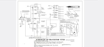
My last project was a Transistor VTVM or FET voltmeter I designed and built.
Dave
Hi RJM1,
I would agree with you normally. For sure, you cannot equate a VTVM with any sort of normal DVM unless it is a DC measurement.. Any AC component and they are different, and difference in loading and you'll be off as well.
I can say with certainty, given normal design for the type, a FET type "VTVM" and A tube VTVM are equivalent. They operate and indicate exactly the same. It is possible a FET type has better HF response, but as long as they present the same loading to the circuit resistively and capacitive, your readings will be just as valid with either. I happen to know this from practice. The FET versions were specifically designed to be equivalent to a VTVM for those reasons.
I do have HP 3400A plus VTVM's, plus a SImpson 260 along with digital meters of various AC detection types. The most major difference is that meter movements (unless driven after an RMS detector) are average responding, some in between ones may be peak responding. That is when you must know your instrument and what you are measuring.
So unless you have an odd (non-standard) FET type meter, yo ucan equate those measurements with those from a VTVM. Of course when making any measurement, you really need to know what the characteristics of your meter and the signal are.
RJM1,
One of my jobs at Tektronix was in marketing as a product support specialist.
I jumped through all kinds of hoops to give world class customer service.
I used to take the 44 Pound 2782 spectrum analyzer, put it in a 41 pound "C5A touch-and-go" protective case, and take it to PDX airport.
I took the 85 pound package to United Airlines counter-to-counter desk, and sent it to Rockwell Collins in Iowa.
C5A touch and go?. . . the desired requirement was the ability for a US Air Force C5A to lower the rear ramp, wait till the wheels squealed,
kick the package out the back, while the pilot immediately gained altitude and flew off.
You can not believe some of the things the military wanted Tektronix to do.
One test I did was to make sure that a 44 pound spectrum analyzer on a nuclear submarine could not come out of an equipment rack . . .
when subjected to a shock of 50Gs (2,200 lbs, a Long Ton).
The sailor would not be cut in two if the spectrum analyzer stayed put; but he might be coming back in a body bag anyway.
Yes, a FET VM may indicate the same reading as a VTVM. but there is no traceability back to the
original measurement. Thus the reading cannot be validated for consecutive measurements.
original measurement. Thus the reading cannot be validated for consecutive measurements.
I am not convinced that most posters and most readers of the Tubes / Valves threads worry about traceability when they measure their tube amplifiers;
And some of them do not have equipment that will give them the proper answer, let alone be traceable to much of anything.
Most of us are not working in a government or commercial calibration lab.
Making the differences between VTVMs and TVMs into a big important issue is for those laboratories, not so much for this thread.
When I was an electronic technician on a US Naval Destroyer in the middle of the Pacific Ocean, and an important communication equipment or important radar was broken, and there were no proper parts on board, I did not wait until we pulled into port alongside a US Naval Tender.
Instead I fixed the equipment even if that meant jury-rigging it.
Fixing it got the chief electronic technician, electronics material officer, and the captain of the ship . . . off my back.
Traceability be damned!
Just my opinion.
Last edited:
The one designed has adjustments for each voltage range ( 0.5 , 1 , 5 , 10 ,50 100 volts)Hi RJM1,
I would agree with you normally. For sure, you cannot equate a VTVM with any sort of normal DVM unless it is a DC measurement.. Any AC component and they are different, and difference in loading and you'll be off as well.
I can say with certainty, given normal design for the type, a FET type "VTVM" and A tube VTVM are equivalent. They operate and indicate exactly the same. It is possible a FET type has better HF response, but as long as they present the same loading to the circuit resistively and capacitive, your readings will be just as valid with either. I happen to know this from practice. The FET versions were specifically designed to be equivalent to a VTVM for those reasons.
I do have HP 3400A plus VTVM's, plus a SImpson 260 along with digital meters of various AC detection types. The most major difference is that meter movements (unless driven after an RMS detector) are average responding, some in between ones may be peak responding. That is when you must know your instrument and what you are measuring.
So unless you have an odd (non-standard) FET type meter, yo ucan equate those measurements with those from a VTVM. Of course when making any measurement, you really need to know what the characteristics of your meter and the signal are.
I have a AC DC probe to 250 volts too. I used a LF353 chip to repace the 12AU7 tube. So far it works great .
Dave
Hi Dave,
That's great. Do the adjustments interact at all? Just asking. A precision divider would be more than sufficient.
Hi RJM1,
NIST anyone? That is your traceability. Direct experience for me as I was a calibration / repair tech, and I design simple test equipment as well as restore and improve test equipment. My bench is mostly HP / Agilent and Keysight.
Found this to be true- single comparo of previously listed equipmentUsually on tube amplifiers the voltage measurements are stated for a tube VTVM on the schematic
or service manual.
Therefore a FET VM will probably not give you the same readings as when your amp was made.
Yes I posted a schematic on what built and how the adjustments work.Hi Dave,
That's great. Do the adjustments interact at all? Just asking. A precision divider would be more than sufficient.
Hi RJM1,
NIST anyone? That is your traceability. Direct experience for me as I was a calibration / repair tech, and I design simple test equipment as well as restore and improve test equipment. My bench is mostly HP / Agilent and Keysight.
Dave
Attachments
Also while working at Collins I was troubleshooting a
microwave transmitter taking voltage measurements with
a Fluke 87 meter and the readings did not look right.
I borrowed a Fluke 87 II which gave me the correct reading.
I sent the Fluke 87 off for calibration and when it came back
they said there was no problem, it passed cal.
So much for NIST traceability in this case.
Different calibrated meters can give different results under
certain conditions. This is why you need to specify the exact tools
that were used to make the measurements if you want them repeatable.
Spiffy DIY...
Always cool when you do it yourself-
I, on the other hand, purchased a Radio Shack 22-220 FET VOM off ebay for $30. Good exterior condition.
Needed lil HCL on the selector switch- then came around nicely
DISCLAIMER
When using Hydrochloric Acid for cleaning contacts... Be advised not to inhale the vapors, allow contact w/ skin... drink or bathe in it
However meter movement is too slow for my liking. My refurb'd Eico 232 needle snaps up to a reading post haste... I like that when probing close proximity nodes in P to P wirings... less chance of a wandering hand creating a short circuit wtg for reading.
Jim
Hi Jim,
I recently bought a Micronta 22-207, a fairly rare beast which I think was second in line to the FET vom range of the day (at 100,000 ohms/v). When I think about it, it does respond slowly; very damped. That's made me think; maybe the two jewels on the movement need lubrication. One of my other hobbies is servicing and repair of mechanical watches, and I have a range of top quality watch oils, so I might lube them with some Moebius 9010 watch oil. Some oils are known to become gummy, one of the things good watch oil avoids.
Strictly speaking they should be cleaned then lubed, but a bit of oil will indicate whether it's the problem. If I get time to have a crack at it, I'll report back.
Cheers
Stuey
Last edited:
Hi Dave,
Nicely done. I would add low capacitance diodes from the buffer amp inputs to supplies for protection. I'll assume your input divider is designed to be slightly high? I haven't bothered to work out the ratios. I like the way you sorted out calibrating each individual range.
Some experimenting with parallel capacitance across your dividers would extend high frequency response on AC. That would seem to be useful. Does it have an AC detection circuit, or is it just DC?
-Chris
Hi RJM1,
I caught Fluke returning out of tolerance meters a few times when sent for cal. This isn't the fault of NIST at all. Also, you must specify the frequency ranges if you are looking outside the specified range, or a special calibration.
Finally, in your case that meter may have had susceptibility to RF in the environment. I am extremely familiar with the 87 series of meters, they do have shields internally. I took old cases and drilled out the adjustment locations in order to calibrate them. That got the HF cal closer because the exact mechanical position of that shield really affects the HF response. It was a lot closer that way, but still changed a fair bit when you installed the correct case. I still have one here (drilled case). I always ran the numbers assembled with the proper case as the customer would receive it. So, just so you know, even changing the battery would shift the HF calibration a bit.
So your comments have nothing to do with the concept. They have everything to do with the skill of the calibration technician (they probably didn't characterise the meter with the case on). That means that lab failed it's certification procedures completely. Anything with my signature was in tolerance, and if you needed to know, your facility should have ordered level 6 calibration which means you get all readings before and after calibration. Not just OOT readings. Your experience is a failure of the calibration process of the lab your company was using. Period.
Yes, you are correct in that different equipment can return different readings. It is up to you to characterise your meter under your conditions. However, in the specific case we are discussing, Fet type VTVMs were designed specifically to replace a tube VTVM exactly - and they did. Generally 2% tolerance, some 1.5% tolerance as I previously stated. Special meters (expensive) may have higher accuracy, and that puts them in a different category. However, changing the active device technology could only change the HF AC performance slightly. The product spec sheet will reflect that. The improved drift characteristics and long term ability to hold calibration were the drivers for that change, instant on didn't hurt either. Same for releasing the instrument from AC power or a lead-acid cell for the heater (and the "B" battery).
So really in a practical sense, any service technician who switched from a classic VTVM to a Fet type got readings every bit as valid, but more accurate and consistent over time. Nothing but positives here. If you want to get picky, resistor value change measuring higher voltages introduced higher errors in common VTVMs. The later Fet types sometimes had better resistive dividers. Specialty meters used the proper resistors. I use 3,500 volt, 1% selected resistors in my VTVMs for high voltage ranges (1.5 KV) and change to 500V resistors around the 100 ~ 150 V ranges and down.
Anyway, to summarize, your experience with the Fluke 87 (mechanical cal) was clearly a failure of the facility your company used. That is one reason we went to "closed case" (electronic) calibration. It has exactly zero to do with your argument - and you brought in a DVM into the mix when we had indicated the meter type had to be the same.
-Chris
Hey Stuey,
Meter movements are dry. Do not lubricate. They may need cleaning, or the tension has increased for some reason. Personally I wouldn't touch a meter movement.
Look at the schematic. The meter drive may well be damped capacitively to prevent the pointer from being launched. Reducing that capacitance may speed up response, but you may also see some overshoot. It's all a compromise.
- Home
- Amplifiers
- Tubes / Valves
- VTVM or FETVM?