Just a thought:
If you are intending to use 6SN7 tubes, the heaters of both tubes need to be in series with each other. It looks from the last pic as if you have them in parallel, which is only good if you are using 12SN7 tubes. The red-to-black DC measurement will be up to 20v with no load, and 12-13v with the tubes in place. A 6SN7 powered like that won't last long.
Please check the wiring before plugging the tubes in under power.
Note the diagram showing different heater supply connections for the 6SN7 and 12SN7 tubes.
The random ac component you are measuring is because there is no tube plugged in. The diodes you used are OK for this job.
Ah, OK. For some reason, at first glance I thought the diagram meant you could do it either way. I will change it in the morning. Thanks rotaspec.
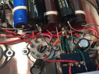
I rearranged the heater wires such that the red goes from 6800uf cap positive lead to pin 7 of tube 1, red from pin 8 tube 1 to pin 7 of tube 2, black from pin 8 tube 2 to the negative lead of the 6800uf cap (attached pic). I believe the 6SN7 sockets are now wired in series per the schematic and would appreciate confirmation before I plug in and test the heater voltage on the tubes, since they weren't cheap.
Btw, the exposed joint where the black wires were soldered together in the pic is now covered with heat shrink.
Btw, the exposed joint where the black wires were soldered together in the pic is now covered with heat shrink.
Attachments
I went ahead and powered it up with tubes in, first the 6SN7s alone and then with the 5Y3GT.
Heaters -- Tube 1: 6.4V | Tube 2: 6.1V
B+ (final resistor lead in HV supply of each channel to ground)
* L -- 379V
* R -- 355V
Cathode 2 voltage
* L -- 134V (right about on target)
* R -- 18V
I don't have the best multimeter, and the results could change frequently while I was measuring. But I did get these numbers multiple times, so I have to think something is wrong somewhere.
Still not ready to play music, I think.
I switched to a different multimeter and got around 133v at both second cathodes and about 3.5V at the first cathodes. Since it seemed like the first multimeter had gone nutty, I decided to plug it in and listen.
Only the left channel works, but it sounds very nice and plays CDs much louder than I could before, which was needed.
I swapped the tubes into the other channels, incase it was a bad tube, but the problem remained at the right. The very last tiny bit of silver solder went into the final weld, so unless it's just a matter of firming up a cold joint in the signal chain, I'll have to wait until the new coil of solder arrives next week.
I'll try swapping interconnects tomorrow but I doubt it's that.
The right channel has a soft rushing sound like a radio station that's off the air. Any idea what that might mean?
Try shorting the input stage grids together. If the right channel plays, then your right channel input circuit is open somewhere. If the left channel goes dead, then your right channel grid is probably shorted to ground.
......
The right channel has a soft rushing sound like a radio station that's off the air. Any idea what that might mean?
Not familiar with 6SN7 but I would suspect self oscillation. It will probably resolve when you get whatever else is wrong sorted out.
Win W5JAG
Thanks for your replies BinaryMike and Win.
I had trouble getting a good ohm reading of the right-channel signal wires at the volume pot -- but I could get one. So I resoldered them anyway.
When inspecting the right channel 6SN7, I tugged the 47K resistor to plate 1 (pin 5) and found that it was actually not attached, moving almost imperceptibly despite the beautiful looking solder weld. That would account for why I was getting readings of 18V and 133V at the same position, as well as a 20V B+ difference in each channel: I must have been pressing it with the multimeter probe hard enough that it made the connection some of the time.
So I resoldered that connection, and now everything is balanced. B+ is 340V in both channels (not 330V as held in VTV Octal lore) and cathode 2 at 130V each channel.
The only real voltage disparity is that the right channel heater measures 5.9V while the left one measures 6.3V, which is odd because the left channel is the latter one in the series, so I'd expect the lower voltage to be there after the resistance in the right channel. The filaments of both tubes light up just fine.
Anyway, PS caps are decharging, and then I'll go listen again.
Well I can report that the stock VTV Octal Linestage works very well in my system. The noise floor is very quiet at idle. It collects a turntable, CD player, and phone/tablet/laptop/whatever and inputs to a Tubelab SE 300B.
The Achilles heel of this system has been CD volume, and it now drives them to gloriously loud SPLs. The TSE seems to be receiving more information too, particularly from CDs, as I hear a little more detail and the soundstage is better defined. The instruments but especially vocals have a more discrete spatial presence, in a good way. The wholeness and unity of the soundstage is improved a little too, since I could still hear everything in the same place when I was leaning over the middle of the system to adjust something and my head was behind the speakers.
My system still doesn't do the 3D thing like the George Wright stuff I've heard, so after this preamp is finalized I'll make a pair of 300B mono blocks with no ICs.
I will let it burn in before making adjustments, as I'm not sure yet what can be improved. But I will post here when I determine what that will be.
Bottom line is that I LIKE what I'm hearing and the TSE is happier with a preamp in front of it.
Thanks to all who have chimed in.
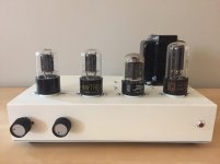
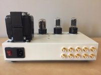
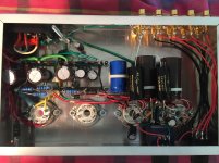
Pics attached for those interested.
The Achilles heel of this system has been CD volume, and it now drives them to gloriously loud SPLs. The TSE seems to be receiving more information too, particularly from CDs, as I hear a little more detail and the soundstage is better defined. The instruments but especially vocals have a more discrete spatial presence, in a good way. The wholeness and unity of the soundstage is improved a little too, since I could still hear everything in the same place when I was leaning over the middle of the system to adjust something and my head was behind the speakers.
My system still doesn't do the 3D thing like the George Wright stuff I've heard, so after this preamp is finalized I'll make a pair of 300B mono blocks with no ICs.
I will let it burn in before making adjustments, as I'm not sure yet what can be improved. But I will post here when I determine what that will be.
Bottom line is that I LIKE what I'm hearing and the TSE is happier with a preamp in front of it.
Thanks to all who have chimed in.
Pics attached for those interested.
Attachments
Last edited:
jdrouin,
Nice work. For an upgrade consider using current sources (a la Bottlehead's Foreplay), to replace the plate resistor in the 1st common cathode gain stage and a current source for the cathode resistor in the 2nd cathode follower stage. You will obtain the full mu (i.e. gain) of the 6SN7 from your common cathode gain stage this way if you need or want that gain. There are several other mods, but enjoy your preamp first before heading that route. It's educational to say the least.
Best,
Anand.
I built this pre-amp, but found the 6sn7's are too microfonic; best to use 6CG7 if you have sensitive speakers mine are 100Db plus
Phil
Phil
The only real voltage disparity is that the right channel heater measures 5.9V while the left one measures 6.3V, which is odd because the left channel is the latter one in the series, so I'd expect the lower voltage to be there after the resistance in the right channel.
Hookup sequence makes absolutely no difference in a series circuit. The heater voltage difference you're seeing can only be caused by a difference in hot heater resistance.
Thanks, multi. I'll keep that in mind. My speakers are 91.5db, and I don't find the 6SN7s to be microphonic.
BinaryMike: thanks for the info.
Well, the wife has taken the kids to a birthday party so I finally have time to sit and do some close listening. This preamp really allows my power amp to blossom. I'm listening to two Flaming Lips albums on CD, Yoshiri Battles the Pink Robots and Oczy Mlody, and the amount of information coming through the speakers is just astonishing. Electronic tones as pure as can be. Incredible transients and texture, particularly in the low end. Really appreciating the 11lbs apiece OPTs (Electra-Print).
I'm having FEELINGS right now.
Last edited:
- Status
- Not open for further replies.
- Home
- Amplifiers
- Tubes / Valves
- VTV Octal (6SN7) Line Stage Build --> Mod