Terry, as far as I know you are the DIYAudio member with the largest collection of amplifier builds...
My bad! resistor values meant to be 750ohms and 820ohms. In my final build I settled for 2 x 1.5k in parallel, that is 1500/2=750. DC offset was 0.6mv.
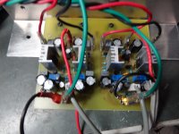
...and my manner of soldering (inspired by thimios soldering method)..my first proto board..

thimios, sorry my friend i'm getting out of topic...
Try to work with the resistor from values of 750k to 920k depending on your PSU rail.
My bad! resistor values meant to be 750ohms and 820ohms. In my final build I settled for 2 x 1.5k in parallel, that is 1500/2=750. DC offset was 0.6mv.
...and my manner of soldering (inspired by thimios soldering method)..my first proto board..
thimios, sorry my friend i'm getting out of topic...
Last edited:
Thanks. I'll probably start with pots so I don't have to solder and unsolder parts too many times. That's hard on home etched boards. That's some very clean soldering. One of these days I will have to learn how to do those measurements like thimios does. That would add to the enjoyment.
Blessings, Terry
Blessings, Terry
Thimios,
I would love know your process for measuring distortion on your various amps. Do you have a piece of equipment that attaches to the output of the amp?
abetir,
I finished the amp based on your layout. I installed 2k pots rather than resistors. I'm running it on +-44V rails and the posts ended up at 470R on one board and 500R on the other with the VAS current set to 14mA when warmed up. I tried a few different rail settings and the VAS current changes with each each rail change so I will leave the pots for flexibility. It would probably be better with 1k pots. I may change those out. This is a nice layout. Easy to etch and build. A 14ma the vas runs pretty hot. I think the little heatsinks are necessary.
Blessings, Terry
Attachments
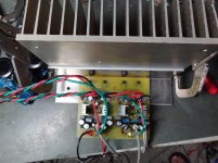
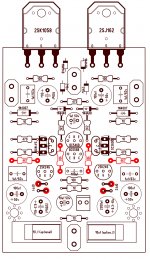
Very nice Terry, at -+44v I'm glad it worked smoothly I have never tried my amp to reach that power level. 🙂 You may want to do some changes to suit your current (-+44v) psu rail (attached changes in red). It looks to me that VAS works at its optimum. On the other hand if the amp shows no sign of instability then leave it be. You've got excellent heatsinking 
All's well that goes well
All's well that goes well
Attachments
New test
Shaan original vers. bd139-140
Shaan original vers. bd139-140
Attachments


Last edited:
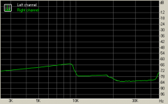
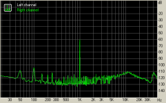
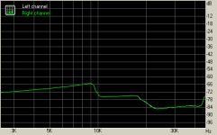
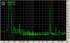
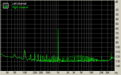
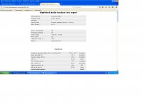
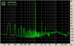
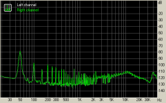
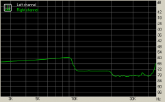
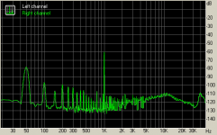
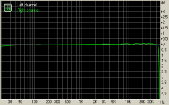
New test
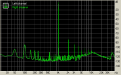
Shaan original vers. with KSA1381 KSC3503.
2)frec.responce
3)dinamic range
4)indermod.distortion
5)IMD
6)Noise level
7)THD+NOISE
Shaan original vers. with KSA1381 KSC3503.
2)frec.responce
3)dinamic range
4)indermod.distortion
5)IMD
6)Noise level
7)THD+NOISE
Attachments

Last edited:
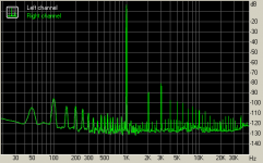
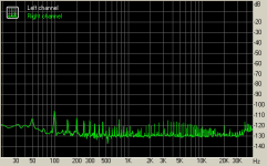
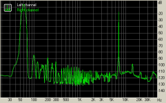
New test
PMI vers.
All these test on a 6R dummy load.
PMI vers.
All these test on a 6R dummy load.
Attachments

Last edited:
Thimios, may be you can experiment to change resistor in emitter input transistors (Shaan version), with jfet current source.
If there is no change or better measurement, the different of Shaan version and PMI version because of PCB layout.
If there is no change or better measurement, the different of Shaan version and PMI version because of PCB layout.
Do you mean,that different measurements is a result of different input transistors current?Thimios, may be you can experiment to change resistor in emitter input transistors (Shaan version), with jfet current source.
If there is no change or better measurement, the different of Shaan version and PMI version because of PCB layout.
Do you mean,that different measurements is a result of different input transistors current?
No, I think it can be different PCB layout (components placement and pattern layout). Example: where feedback point is taken, etc.
What would you like to prove, that resistor is better than CCS? If you use shitty CCS is exactly what you came across here. VSSA module measures far better than resistor only CCS. I made this kind of measurements some two years ago.Do you mean,that different measurements is a result of different input transistors current?
What would you like to prove, that resistor is better than CCS? If you use shitty CCS is exactly what you came across here. VSSA module measures far better than resistor only CCS. I made this kind of measurements some two years ago.
I agree.
You should replace Shaan version with CCS and replace PMI version with resistor only CCS. And take some measurement.
I like the apples vs apples comparison going on here. 😉 😎 The plots and the numbers add up nicely to the amp's sonics!  Hat's off to you, Terry and abetir! Keep up the good work guys, you rock!
Hat's off to you, Terry and abetir! Keep up the good work guys, you rock! - Status
- Not open for further replies.
- Home
- Amplifiers
- Solid State
- VSSA PMI version vs Peeceebee Shaan version