I set firmly the values since these are calculated and very important to consider. Also 10 uF MKT is of utmost importance to be in the circuit, tested at MHz bandwidth region. 
Above applies also to the PSU local (PCB) capacitors , I'm talking about those 1000uF ???
Above applies also to the PSU local (PCB) capacitors , I'm talking about those 1000uF ???
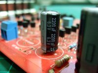
I mainly use Panasonic FR nowadays. They have the same low ESR then FM but have double the life span. They are very affordable and i can get them from Reichelt in a day.
I used FR in my poor-man's through-hole version of VSSA/PeeCeeBee.
I hope to compare to LC's boards within a week, using the caps he recommended. I try to follow directions first time I build someone else's design, on the theory that making changes before having anything to compare is a bad idea, at least for someone with limited knowledge (tested that theory thoroughly... 😀)
I have noticed far bigger dependency on power supply quality than what I expect to see using different on-board caps (assuming similar ESR etc).
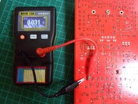
Measuring an FR 2200uF 6.3V for ESR in circuit on Paradise phono gives 0.031 Ohm which is usually 0.01 less for this instrument if measured off circuit to grip the leads better. (Went there if I firmly pressed the crocks down in circuit also, 29C ambient). That one ties with the 0.020R 100kHz 20C for its 20x10mm size can @6.3V in Panasonic's datasheet. Reliable data.
Attachments
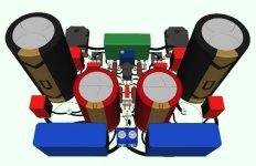
Very nice chassis! I like the stealth on-off switch!Few pics of a new VSSA case, dual mono design with SMPS400A180 naturally. 🙂
Nice toy, I am jealous! 😀Measuring an FR 2200uF 6.3V for ESR in circuit on Paradise phono gives 0.031 Ohm which is usually 0.01 less for this instrument if measured off circuit to grip the leads better. (Went there if I firmly pressed the crocks down in circuit also, 29C ambient). That one ties with the 0.020R 100kHz 20C for its 20x10mm size can @6.3V in Panasonic's datasheet. Reliable data.
If you haven't got an LCR don't spend on a separate ESR meter, get a good LCR that includes the function, also DF & Q. Best handheld is IET DE-5000.
Measuring an FR 2200uF 6.3V for ESR in circuit on Paradise phono gives 0.031 Ohm which is usually 0.01 less for this instrument if measured off circuit to grip the leads better. (Went there if I firmly pressed the crocks down in circuit also, 29C ambient). That one ties with the 0.020R 100kHz 20C for its 20x10mm size can @6.3V in Panasonic's datasheet. Reliable data.
Salas! I have seen a few "different" MESR-100. I think yours is the latest one. I saw one of this meter open and I saw TWO ELECTROLYTIC caps inside. I am not sure if your is the same, but if it is...I would measure them to make sure those electrolytic caps are still good. imagine an E.S.R meter with bad caps! That MESR-100 E.S.R meter looks way better build than those "ATLAS" plastic toys meters.
They could be peripheral to the chip, everything is OK as long as it manages to auto zero. Those 44/100 HRC 35mm fuses for the 87V are ouch priced BTW. I blew one recently.😀
Few pics of a new VSSA case, dual mono design with SMPS400A180 naturally. 🙂
I love the look of the chassis. Where does it come from?
Hi all,@PMI
Was it Elna & Blackgates?
so Elna & Blackgates is not good?
I try to make PCB with 680uF BGF & 2200uF/16v Elna Cerafine...
I'm also want to put more voltage +/-50VDC maybe, how to make CCS for it?
I have few K170 & K246, they can't use with that voltage right
Thanks
Attachments
Does anyone have part numbers for alternative capacitors since the FGs seem to be a bit hard to come by?
Nichicon KA Series?
Panasonic FR?
I'd prefer to order all caps in one go so as not to be beaten to death on shipping.
Nichicon KA Series?
Panasonic FR?
I'd prefer to order all caps in one go so as not to be beaten to death on shipping.
If you order at Mouser the will send backordered FG separately from rest of your order free of charge, at least that is what they offered me (and I said No I will wait 🙁 )
Dear LC,
It would be interesting to see the DC output of the SMPS on a scope...how clean they are?
I am inclined to use regulated supplies these days...
Regards,
M.
It would be interesting to see the DC output of the SMPS on a scope...how clean they are?
I am inclined to use regulated supplies these days...
Regards,
M.
I will use 225VA trafo, 8x switch diodes, 20x 2200uf, each channel
but then, in 40V series you can get some pretty nice and big longlife 22000uf at ok prices
4x 22000uf per channel ?
but then, in 40V series you can get some pretty nice and big longlife 22000uf at ok prices
4x 22000uf per channel ?
but then, in 40V series you can get some pretty nice and big longlife 22000uf at ok prices
4x 22000uf per channel ?
I guess it is a trade off. but remember the more parts you put...the more are the chances they can go bad. in my case I would not use more than four caps for the power supply, as long as they are good quality and low E.S.R...all will be good!
PS: I always use Mundorf audio grade caps in my power supplies. They are excellent!😉
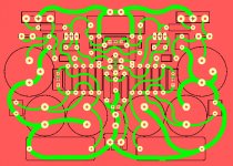
Capacitor dimensions for VSSA PCB:
- 10 uF/63 V, MKT, Vishay-Roederstein, 2 pcs
Lead Spacing: 15 mm
External Depth: 8.5 mm
External Height: 17.5 mm
External Width: 18 mm
Regards Lazy Cat
I am searching for the MKT and I find this Vishay-Roderstein, MKT, 10uF 63V on Mouser's stock list: 75-MKT1822610065
Lead spacing is 27.5mm much larger than your spec. Can you point me to the one you used?
Thanks.
I am searching for the MKT and I find this Vishay-Roderstein, MKT, 10uF 63V on Mouser's stock list: 75-MKT1822610065
Lead spacing is 27.5mm much larger than your spec. Can you point me to the one you used?
Thanks.
This one is about the same size and quality. MKS4B051004J00KSSD WIMA | Mouser
Member
Joined 2009
Paid Member
Well I have been watching closely - this is a fantastic result (amplifier design and pcb layout) LC. You kept it simple in layout and in physical form. I know you promised that you'd do this but it isn't easy and it turned out very well indeed.
I think this has turned out to be the 'F5' of the SS forum (meant as a compliment).
The LatFET is so well suited to this topology because of the ease of thermal compensation and ease of drive. The two-in-one package for the FETs was really the icing on the cake.
I think this has turned out to be the 'F5' of the SS forum (meant as a compliment).
The LatFET is so well suited to this topology because of the ease of thermal compensation and ease of drive. The two-in-one package for the FETs was really the icing on the cake.
- Home
- Vendor's Bazaar
- VSSA Lateral MosFet Amplifier