CFA Circlotron
HI
I tried to simulate a VSSA CIRCLOTRON but i have no gain ...
Must I add a follower after VAS ?
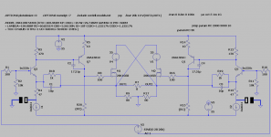
corrected schematic : it works

https://sites.google.com/site/opampbasedamp/CircloVSSA.asc
Could you help me ?
Thanks
HI
I tried to simulate a VSSA CIRCLOTRON but i have no gain ...
Must I add a follower after VAS ?
corrected schematic : it works
https://sites.google.com/site/opampbasedamp/CircloVSSA.asc
Could you help me ?
Thanks
Last edited:
Hi UltimateX86,
I can't run your simulation right now but I think it will work in principle. I'd suggest checking all DC operating points with no signal to be sure they're where they belong.
Also, V2-V3 can be 24V or less, and the PNPs can be small signal devices idling at 5-10 mA. These changes are optional but may reduce build cost somewhat.
As jerluwoo point out added two caps to schematic. I'm not sharp in construction but noticed the VSSA originals didn't swing or make gain if this cap missed. The VSSA originals used 470-2200uF/6,3V and some even bypassed the elco with 10uF MKT. The more value for the elco the lower the -3dB highpass in LF region, and more linear group delay down there.
EDIT if this will do and you build it, beware that this cap influence the sound quality as it were sitting as a coupling cap in hot signal, therefor if seeking high quality sound performance pick caps value/bypassing/quality/cost as scenario prefered.
EDIT if this will do and you build it, beware that this cap influence the sound quality as it were sitting as a coupling cap in hot signal, therefor if seeking high quality sound performance pick caps value/bypassing/quality/cost as scenario prefered.
Attachments
Last edited:
Or, instead of adding the caps, you could replace R4 and R13 with a single resistor tied between the emitters of Q2 and Q3.
HI
Yes I forgot capacitors but even with, no gain : 1V in = 1V out
Joe, so this will made a differential pair ?
Yes I forgot capacitors but even with, no gain : 1V in = 1V out
Joe, so this will made a differential pair ?
Last edited:
HI
I tried to simulate a VSSA CIRCLOTRON but i have no gain ...
....
Could you help me ?
Thanks
What is the value or R15 and R20?
Interesting concept. When're can I find more info on this design?
FB
Last edited:
THANKS
I had misplaced the capa, It Works
THD 20K 1W 8ohm : 0.000067%
THD 20K 50W 8ohm : 0.002758%
https://sites.google.com/site/opampbasedamp/CircloVSSA.asc
I had misplaced the capa, It Works
THD 20K 1W 8ohm : 0.000067%
THD 20K 50W 8ohm : 0.002758%
https://sites.google.com/site/opampbasedamp/CircloVSSA.asc
Last edited:
Hi UltimateX86
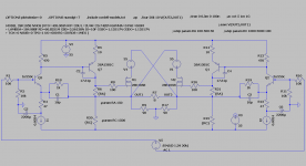
Try to replace R20 & R15 (RC) with suitable two CCS , or divide both R20 & R15 and insert two bootstrap electrolytic caps in between of that divided res.networks.
Best Regards !
Try to replace R20 & R15 (RC) with suitable two CCS , or divide both R20 & R15 and insert two bootstrap electrolytic caps in between of that divided res.networks.
Best Regards !
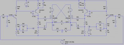
Rather than having a huge 2200uF resistor, i'd prefer replacing the CCS with resistor. A CCS on a common emittor is unusual.. Any voltage swing on the base will just be consumed by the CCS, leaving no voltage swing on the cathode.
Attached is my version on your amp. This would be an expensive amp on the power supply side, especially if stereo.
edit: RC is 2 kohm
Attached is my version on your amp. This would be an expensive amp on the power supply side, especially if stereo.
edit: RC is 2 kohm
Attachments
Last edited:
HI Banat
I have to put the capacitor between how?
(edit) I had not refreshed the page, thanks Ballpencil
I have to put the capacitor between how?
(edit) I had not refreshed the page, thanks Ballpencil
Attachments
Last edited:
HI Banat
I have to put the capacitor between how?
Ballpencil allredy show the solution in his version of schematic .(post #11)
HI ballpencil
could you share the ASC file ?
Without CSS .. ok
I already have two tr of 2X25V 400VA and lot of BC154 caps
Must I add a follower after VAS ?
could you share the ASC file ?
Without CSS .. ok
I already have two tr of 2X25V 400VA and lot of BC154 caps
Must I add a follower after VAS ?
Last edited:
Rather than having a huge 2200uF resistor, i'd prefer replacing the CCS with resistor. A CCS on a common emittor is unusual.. Any voltage swing on the base will just be consumed by the CCS, leaving no voltage swing on the cathode.
Attached is my version on your amp. This would be an expensive amp on the power supply side, especially if stereo.
edit: RC is 2 kohm
Hi Ballpencil !
Just a thought that OPS both ground reference resistors (R13&R17=1K) are way to high in value , think that anything between 47R and 100R will be better choice .
Best Regards !
Rather than having a huge 2200uF resistor, i'd prefer replacing the CCS with resistor. A CCS on a common emittor is unusual.. Any voltage swing on the base will just be consumed by the CCS, leaving no voltage swing on the cathode.
Attached is my version on your amp. This would be an expensive amp on the power supply side, especially if stereo.
edit: RC is 2 kohm
I found 4A bias 😱😱 and lower gain
Last edited:
Attached..
You may need to play with the values a bit.. FFT profile is not as good as your CCS version.
Ah yes.. bias was too high. I got 100mA bias once but the sinewave output was skewed. As i said, you need to play with the values.
You may need to play with the values a bit.. FFT profile is not as good as your CCS version.
Ah yes.. bias was too high. I got 100mA bias once but the sinewave output was skewed. As i said, you need to play with the values.
Attachments
Last edited:
HI ballpencil
Must I add a follower after VAS ?
I think some followers is must but just in case if you want to drive multiple pairs of power output LatFets .
Forget using my version :🙁 I tried playing with it more but i can't seem to get better performance.
Yours is much better. CCS on common emitter will work. No, the CCS will not consume the voltage swing on the cathode as BJT works with current, not voltage. Sorry..
Yours is much better. CCS on common emitter will work. No, the CCS will not consume the voltage swing on the cathode as BJT works with current, not voltage. Sorry..
- Status
- Not open for further replies.
- Home
- Amplifiers
- Solid State
- VSSA Circlotron