He will not get full volume as arriving at the trimmer.
The extra resistor is in series with the Rin of the receiver.
The attenuation during the period of switch over will be 20log(Rin/{Rin+Rextra}),
i.e. 20 log (47k / {47k+47k} )= ~-6dB, or roughly the same as the volume set by the trimmer when turned to 50%.
But most of the trimmers will probably be set to maximum, or near maximum. The master control sets the voume for the house.
If he used 20k for the extra resistor and had the trimmer set to 50%, then for the 1ms of change over the volume would go up by ~3dB and then become muted. But if the trimmer was set to 70%, there would be no change in volume during the 1ms of change over.
Last edited:
Mooly & Andrew,
Thanks for all the thought and consideration going into my "simple" zoned volume control concept. Its going to take me awhile to process this. I'm going to try to draw up the full L & R schematic of everything discussed. Drawing it seems to help me develop my understanding of the concepts. Its also helping me to understand how to read a schematic.
But for now, I have toddlers to tend to and NFL playoffs to watch 🙂

The opamp isn't configured correctly. Input to pins 3 and 5 as you have. For a buffer we connect the inverting input directly to the output, not to ground.
I'm not totally convinced by Andrews arrangement tbh as it all depends on how the switch behaves. If the moving contact of the switch doesn't connect to either of the other terminals as it moves across then you will very loud audio as the amp is fed directly via 20k.
What's wrong with just tying the amp input to ground via a high value resistor, say 47k. That way the amp input is terminated should the switch float for an instant.
Attachments
He told us a long while back that the amplifiers have an input impedance of 47k.
That means the 47k is already installed, you don't need another.
That means the 47k is already installed, you don't need another.
47k input impedance doesn't mean there is 47k to ground.
Think of a single rail (I think the power amp is single rail Class D) with an AC coupled inverting input stage. The input impedance might be 47k but there doesn't have to be anything directly from input to ground.
Its an unknown without having an accurate diagram of the power amplifier.
Terminating the input connection to the amp with a resistor to ground and its job done for any possible conditions that could arise.
You don't agree I think 🙂
If the input impedance is 47k, then that is what the trim+mute sees.
With a 47k added resistor between the source (after the master+Buffer) and the amplifier the attenuation of signal will be 47k(Rin)/{47k(Rin)+47k)Radd} = -6dB
That is the same volume as having the trimmer set to 50%.
If the trimmer is set very low, for example to 10%, then while the moving contact is between poles, there will be a big increase in volume in that room.
10% gives ~-20dB and the mute pulse will be at -6dB, equalling an increase for 1ms of ~14dB
I agree that would be a loud pulse.
An inverting amplifier which sets it's gain using the total of the source impedances is rather different.
I would never recommend using an inverting input where cables can be disconnected.
Last edited:
47k input impedance doesn't mean there is 47k to ground.
Think of a single rail (I think the power amp is single rail Class D) ...
Actually, the amps input impedance is 22k. It does run on single rail power.
Brian... the actual input impedance isn't really a major concern, it just gives a ballpark figure to work to and to know what to expect when we couple things to it 🙂 What we are trying to achieve is a universal (will work with any amp) design that offers as silent and unobtrusive switching as possible.
Andrew, we will have to agree to differ on this... I'm still not keen on your proposed method. Source impedance affecting overall 'gain' still applies to non inverting configurations as far as the end user is concerned, even if technically it has then becomes a case of signal attenuation (divider action of source and input impedances in series) rather than an actual gain change in the case of an inverting stage.
Andrew, we will have to agree to differ on this... I'm still not keen on your proposed method. Source impedance affecting overall 'gain' still applies to non inverting configurations as far as the end user is concerned, even if technically it has then becomes a case of signal attenuation (divider action of source and input impedances in series) rather than an actual gain change in the case of an inverting stage.
I'm not totally convinced by Andrews arrangement tbh as it all depends on how the switch behaves. If the moving contact of the switch doesn't connect to either of the other terminals as it moves across then you will very loud audio as the amp is fed directly via 20k.
Would a 2 position 2 pole shorting rotary switch work better? I understand this type of device is a make before break style of switch. Wouldn't this avoid the momentary volume increase issue?
The downside to this being cost. Looked at Mouser and Digi-Key; that style seems to be $10 to $20 per switch.
Yes, make before break would stop the issue.
Can you get anything like the Lorlin brand ? These have adjustable stops so can be configured as a two pole two way.
LORLIN - CK1037 - SWITCH, 4POLE, 3 POS | CPC UK
Can you get anything like the Lorlin brand ? These have adjustable stops so can be configured as a two pole two way.
LORLIN - CK1037 - SWITCH, 4POLE, 3 POS | CPC UK
Yes, make before break would stop the issue.
Can you get anything like the Lorlin brand ? These have adjustable stops so can be configured as a two pole two way.
LORLIN - CK1037 - SWITCH, 4POLE, 3 POS | CPC UK
Looks like Mouser does have Lorlin switches. It's not obvious from their search filters that the positions are adjustable through stops. Had to drill through to the product documents to see that. Thanks for the tip!
They have a little collar with a tab that you put in the appropriate slot. Its under the fixing nut.
Lorlin do loads of switches so check any you look at are make before break.
Lorlin do loads of switches so check any you look at are make before break.
So if the zone on/off switch is the shorting variety, are either of the resistors that Mooly or Andrew proposed necessary? I am interpreting these are components that were proposed to avoid volume fluctuations as as a break-before-make switch was thrown.
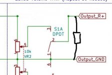
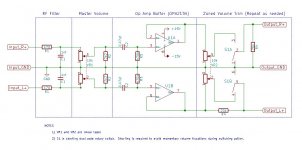
I've updated the schematic to correct the errors I made earlier. The "Zoned" section contains both approaches to the switching problem.
... or at least my understanding of the approaches.
- Upper (R) section is Mooly's approach
- Lower (L) section is Andrew's approach
... or at least my understanding of the approaches.
Attachments
That (upper) is how I would do it. The resistor is really to just 'terminate' the input to the amplifier under all possible conditions which would include the switch if it wasn't make before break, if the switch went a little 'crackly' years down the line and also if the pot went a little noisy years down the line. The absolute value is not critical for that duty, 20k or 200k it wouldn't matter.
A make before break switch is an unusual operation.
It is used for stepped volume controls and similar, but rarely for anything else.
Because Pin1 gets shorted to Pin2 and to Pin3 during the switch over of a make before break.
Most switches are break before make and this leaves Pin1 never shorted to Pin3 during any operation.
It is used for stepped volume controls and similar, but rarely for anything else.
Because Pin1 gets shorted to Pin2 and to Pin3 during the switch over of a make before break.
Most switches are break before make and this leaves Pin1 never shorted to Pin3 during any operation.
In the upper diagram, the 22k for Rin and 20k at the output of this switcher/trimmer sets the load on the 10k trimmer to ~ 10k5.
The linear trimmer will move slightly towards non linear due to this heavy loading.
eg out1 = load set to infinite, out2 = load set to 10k5
rotation out1 . . out2
100% . -0dB . . -0dB
75% . . -2.5dB . -3.9dB
50% . . . -6dB . -7.9dB
25% . . -12dB . -13.5dB
10% . . -20dB . -20.7dB
You may want to calculate the effect on trimmer output and on the noise from the amplifier with the 20k reduced to 10k.
Last edited:
- Status
- Not open for further replies.
- Home
- Source & Line
- Analog Line Level
- Volume Potentiometer Sizing and setup