Agreed the make before break is an unusual choice to have to specify for this. I still feel my option of a simple resistor to ground covers all bases so to speak.
Noise contribution due to the different approaches must be negligible in the overall scheme of things.
10k over a 20k bandwidth @ 25C will generate something like 1.8uV (-115dbV), a 20k resistor around 2.5uV (-112dbV)
Inserting that kind of noise contribution in the middle of a signal chain that ends in a Class D amp isn't going to make any difference at all.
I still advocate the simple resistor to ground which also allows freedom of choice in the switch.
I suppose the simplest path forward is to test the various configurations proposed.
Though it'll have to wait a bit. The Sure 4 x 100 Class D amp I purchased isn't working 100%. Only 2 of the channels will drive speakers. The other two seem to be dead. Sounds a bit hollow too - but made that's just the nature of the amp & speaker combo. I have nothing to compare against. I have an email in with them, but no response yet.
Thanks for all the help!
Can't help much with the amp I'm afraid. Sounding 'hollow'. Are your speakers phased correctly ?
Can't help much with the amp I'm afraid. Sounding 'hollow'. Are your speakers phased correctly ?
I'm fairly certain the issue is with the amp itself. I tried various combinations of inputs, cables, and speakers (I have two sets) on each pair of channels. 1 & 2 work, 3 & 4 don't.
Not going to worry to much about the sound quality until a I get the amp working 100% or get a replacement. If sound quality is still lacking, I'll start a new thread in the Class D amp forum to get some assistance diagnosing the issue.
I was reading up a bit more on the OPA2134 opamp I was considering. I attached a reference from TI documentation. Would the output from U1 in the schematic in post #37 be inverted? The schematic I put together looks to be the same topology as TI's inverting example.
If it is inverting, is this an issue?
If it is inverting, is this an issue?
Attachments
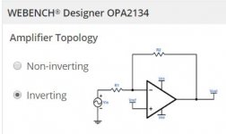
Post #37 is non inverting and is just a buffer.
With opamps remember this 'rule'.
The output of an opamp with feedback (so that's all audio applications) will do whatever is necessary to bring the voltage difference between the two inputs to zero. Note the word difference.
So in the diagram above you have the + input tied to Vref. Let us say Vref is ground and the opamp is running on a standard -/+ split supply.
If R1 was 10k and R2 100k then the output would settle to zero volts (ground potential).
If we apply plus 1 volt to the input, the output has to now become minus 10 volts to maintain our zero volts difference between the input pins.
So we have an amplifier of gain -10 . In other words an inverting amplifier.
Apply minus 1 volt to the input, and the output must go to plus 10 volts to maintain the zero volt difference.
Inversion of phase isn't generally regarded as an issue in audio, in other words you actually can't tell by listening whether the phase is 180 degrees out or not. You can prove that by swapping both speaker leads around in a stereo set up connecting plus to minus for each speaker.
Your buffer in post #37 has 100% negative feedback. If you apply 1 volt to the input, the output must also reach plus 1 volt to maintain a zero volt difference between the two inputs. So you have a buffer of gain = 1
I started a new thread about the power supply for my little project. The conversation led back to why do you need a dual supply opamp.
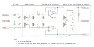
I had originally proposed using the dual supply OPA2134. I've included the schematic from post #37. Would I need to alter the circuit to make use of TL972 instead? Other than adjusting the pin-outs on the IC.
I reviewed the technical doc for the TL972 and it looks like the negative supply would go to ground and the positive would only need a bypass cap from the single supply to ground. TI specs this as a a low-ESR, 0.1-μF ceramic cap.
I choose the TL972 because the SMPS I'm looking at has a 12v auxilary output. Most of the single supply opamps I found on TI's site used a 3v to 5v supply. The TL972 allows for a 12v supply which matches well with by proposed power supply and comes in a through-hole package.
Attachments
don't use a 12V rated opamp on a nominal 12Vdc supply.
Can you elaborate?. The TL972 has a voltage range of 2.7 V to 12 V with a max voltage of 15. Why should a regulated 12v supply be avoided?
don't use a 12V rated opamp on a nominal 12Vdc supply.
is the proposed opamp 12V or 15V?Can you elaborate?. The TL972 has a voltage range of 2.7 V to 12 V with a max voltage of 15. Why should a regulated 12v supply be avoided?
The tech docs state: "Recommended Operating Conditions: 2.7 V to 12 V".
They also state: "Absolute Maximum Ratings: Vcc Supply voltage range 2.7V to 15V"
If the power supply I'm looking at is a regulated 12v, why should this be avoided?
They also state: "Absolute Maximum Ratings: Vcc Supply voltage range 2.7V to 15V"
If the power supply I'm looking at is a regulated 12v, why should this be avoided?
the opamp is specified as 2.7V to 15V.The tech docs state: "Recommended Operating Conditions: 2.7 V to 12 V".
They also state: "Absolute Maximum Ratings: Vcc Supply voltage range 2.7V to 15V"
If the power supply I'm looking at is a regulated 12v, why should this be avoided?
that is OK on a 12Vdc supply.
- Status
- Not open for further replies.
- Home
- Source & Line
- Analog Line Level
- Volume Potentiometer Sizing and setup