Hi,
I'm new to DIY Audio and electronics in general. For my first project, I'm trying to assemble a whole house audio system. Its just for background music, not critical listening.
I purchased a Sure Electronics 4 x 100 Watt Class D Audio Amplifier Board - STA508 (part number AA-AB009). If I can get this working, I'll eventually buy another amp for a total of 8 channels into 4 zones, driving 8 speakers at 8 ohms. I tested this out with my iPhone as a source, speakers jury-rigged on a dinning table and a laptop power supply and its functioning (my first victory 🙂 ).
I'd like to add a master volume control and individual zone volume controls. Not looking to spend a lot at this point, so I was looking at basic audio taper volume potentiometers. I understand these aren't as clean as a stepped attenuator or active IC controller, but I'd like to start simple and low cost and work my way up as needed.
My thought was to send the input into a master stereo volume control pot and then wire the output from this pot in parallel to individual zone specific stereo volume pots (up to four zone specific pots). Does this approach sound reasonable?
I'm having trouble determining what size pots to use. The specs on the amp indicate its input impedance is 22k ohm, and the source will likely be an iPhone. Any guidance on selecting the size for the pots? Also, if the zone will not be in use (such as outdoor speakers in winter), is a volume pot turned down all the way good enough, or should I add some type of on/off switch as well for the zone specific inputs?
Finally, any suggestions on a manufacturer for the pots, our should I just look for low price, using a supplier like Mouser?
So, to summarize:
Apologies in advance if this has been covered elsewhere. I've been searching for days and haven't been able to answer my questions.
Thanks everyone!
I'm new to DIY Audio and electronics in general. For my first project, I'm trying to assemble a whole house audio system. Its just for background music, not critical listening.
I purchased a Sure Electronics 4 x 100 Watt Class D Audio Amplifier Board - STA508 (part number AA-AB009). If I can get this working, I'll eventually buy another amp for a total of 8 channels into 4 zones, driving 8 speakers at 8 ohms. I tested this out with my iPhone as a source, speakers jury-rigged on a dinning table and a laptop power supply and its functioning (my first victory 🙂 ).
I'd like to add a master volume control and individual zone volume controls. Not looking to spend a lot at this point, so I was looking at basic audio taper volume potentiometers. I understand these aren't as clean as a stepped attenuator or active IC controller, but I'd like to start simple and low cost and work my way up as needed.
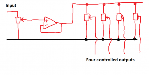
My thought was to send the input into a master stereo volume control pot and then wire the output from this pot in parallel to individual zone specific stereo volume pots (up to four zone specific pots). Does this approach sound reasonable?
I'm having trouble determining what size pots to use. The specs on the amp indicate its input impedance is 22k ohm, and the source will likely be an iPhone. Any guidance on selecting the size for the pots? Also, if the zone will not be in use (such as outdoor speakers in winter), is a volume pot turned down all the way good enough, or should I add some type of on/off switch as well for the zone specific inputs?
Finally, any suggestions on a manufacturer for the pots, our should I just look for low price, using a supplier like Mouser?
So, to summarize:
- Validation or recommended changes to my master volume and individual zone volume approach.
- What size volume pot is recommended?
- Is a signal on/off switch to each zone needed before the volume pot to effectively disable it?
- Any recommendations on a brand/source for the pots?
Apologies in advance if this has been covered elsewhere. I've been searching for days and haven't been able to answer my questions.
Thanks everyone!
Welcome to diyAudio 🙂
OK, some thoughts...
A master pot feeding four others could result in a little interaction as individual levels are altered. It might be workable as a starter project but ideally the master control should be buffered (with a X1 amplifier) that would then feed the other four pots.
Could you get away without the buffer... probably, as long as you accept its not the perfect solution.
Pot values...
Master pot. This depends on the signal source driving the master pot. If we go non buffered then lower is better as long as we stay within acceptable limits. Most modern equipment should drive a 2k pot with ease.
The four other pots... for non buffered these need to be as high resistance as practicable which probably means going for 22k or 47k.
Audio taper (logarithmic) pots are fine but can suffer channel matching between gangs. A linear type is better in that regard and the addition of a single fixed resistor from the wiper to ground does a great job of faking a log law. Win win situation.
Scroll down to near the bottom of page and look at changing the law of a potentiometer.
Potentiometers (Beginners' Guide to Pots)
You don't need a switch to isolate each zone unless that is a feature you want. Any good quality pot should be fine... don't pay to much at this stage. Examples from the likes of OMEG are perfect.
Thanks Mooly! That helps a lot... but does of course lead to additional questions. I'm new to this, so I'd like to offer my understanding of some of your comments. Can you please clarify if I've misinterpreted anything.
You indicated that the master volume should be buffered and mentioned an X1 amplifier. When I google this it keeps taking me to Comcast Infinity links. Are you referring to a Pass X1 style preamp?
I've read similar comments about buffering signal inputs, but am not entirely clear what this means. After some more googling I found this thread. to paraphase, is buffering a component of an active pre-amp, which takes higher impedance signal input and outputs a lower impedance signal. Is the goal to gain voltage, current or both? Or am I misinterpreting.
Without this, is the problem that the signal coming out of the master volume is too weak to effectively pass through the second "zone-level" volume pot without problems? Again, sorry if these are very basic questions. I'm reading through several books on these topics trying to get educated.
For the master volume control, is this setup similar to what you described as buffered:
This is getting more complex, but closer to my long-term goal. I believe the output from this preamp could then be wired in parallel to the individual zone level volume pots (linear tamper with a resistor as you suggested).
Thanks again!
The kind of buffer I'm referring to would be a simple opamp (operational amplifier) configured as a 'voltage follower'.
http://www.eecs.tufts.edu/~dsculley/tutorial/opamps/opamps5.html
The only practical problem with any buffer is that you need a power supply. It is easy to make the opamp run on a single supply in the 12 to 36 volt range with just a handful of parts.
The buffer has a high input impedance and so doesn't load the source it is connected to, in this case the wiper of the master control. The output is likened to a constant voltage such that it is unchanged by whatever load you drive.
It would look like this, although if you wanted to run it off the same supply as the main amplier then you would need a few other parts such as an input and output coupling capacitor and a simple bias network consisting of a couple of resistors.
That kind of circuit can be built on stripboard in a few minutes.
Attachments
I want to suggest you allow for more than one source to be sent around the house.
You have 4 stereo cables feeding independent amps and speakers.
It is fairly simple to arrange two outputs from the source/s (A & B)
This would feed two master stereo attenuators into two stereo Buffers.
The four tappings for the local attenuators could be switchable to either output A or output B.
This adds a lot of flexibility to how the system is used.
I would tend to have local control of the local attenuator. This could be by "remote" control. Or you could move the four local attenuators into their own area to feed their own amplifiers.
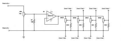
Made my first attempt at a circuit schematic. Does this look right?
The SMPS power supply (Connex SMPS300RS) I was looking at for the power amp has auxiliary +-15V outputs. I was planning to use this to power the opamp (U1).
With the buffer in place, not sure what values to use for VR1 / R1 and VR2 / R2. I took a guess for VR1 / R1, based on Mooly's earlier post. This is assuming linear taper pots and 1% resistors. Would VR2/R2 use the same sizing?
Also, I now understand the purpose for the buffer between the master (VR1) and zone (VR2) volume pots. Is there any benefit to placing a buffer between the zone volume pot (VR2) outputs and the power amp input? I'm assuming no?
Attachments
That looks pretty good 
A couple of things to look at...
1/ With a buffer we can use a more reasonable value of pot for the master control because it doesn't have to take account of loading of the other four. So I would suggest 10k or 22k as a good all rounder.
2/ The same value can be used for the other four. The resistor on the wiper needs scaling to suit of course.
3/ The FET opamp such as the OPA2134 is a good choice. FET opamps have virtually zero DC offset and that means you can often dispense with any output coupling caps, however it might be wise to add one at the input to the opamp.
4/ The opamp should have a small capacitor of say 10uf 63volt connected across the supply pins for local decoupling. Opinions vary... one cap like this, or two with each connected to the appropriate rail and ground. I think one would be fine.
5/ It might be beneficial to also add an RF filter to the input to keep out high frequency noise and rubbish.
I'll draw it out a little later all being well.
So, and accepting there are many way to do this...
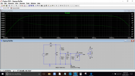
The diagram shows your opamp with the addition of:
1/ Cin and Rbias. These components roll the gain off to zero at DC (a good safeguard for the power amps).
The value of Cin and Rbias form a high pass filter. If the cap is made smaller, the low frequency response doesn't go as low.
Rbias is also needed to set the correct DC conditions on the opamp because the cap Cin has isolated the opamp input from having a DC path to ground. For this function alone the value can be anything from a short circuit to 100's of meg ohms. However 470k and 0.47uf gives a decent low frequency response and allows Cin to be a small film type cap.
Rpot1 and Rpot2 and Rlaw are simply your pot and law faking resistor, set here to 25% rotation by the values entered for Rpot1 and Rpot2.
Rf1and Cf1 filters any high frequency rubbish to ground. Its up to you whether to include these or not. You can see the effect on the rolled off response at HF as shown here.
The cap across the opamp supply isn't shown.
Attachments
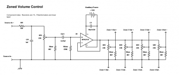
Here's my schematic updated from your comments. This uses one half of the OPA2134 and would be duplicated to produce a stereo input.
The input source will eventually derive from a source selector switch. Would that require any changes to the design?
The input source will eventually derive from a source selector switch. Would that require any changes to the design?
Attachments
Started searching mouser and digikey for available pots. Options seem limited for dual gang linear pots without detent.
In addition, I assume I want conductive plastic elements since this will see frequent use? Is that correct?
With those filters in place, it looks like I'll be limited to 10k pots. Does that mean the related resistor should be in the 2000 to 2500 range?
In addition, I assume I want conductive plastic elements since this will see frequent use? Is that correct?
With those filters in place, it looks like I'll be limited to 10k pots. Does that mean the related resistor should be in the 2000 to 2500 range?
Adding a source selection switch up front requires no changes.
A 10k pot for the input is fine. Any modern source component will drive that with ease. Its things like old DIN standard gear from the 70's that would have a problem, or valve preamp output stages.
20k
3310H-001-203L Bourns Inc. | Potentiometers, Variable Resistors | DigiKey
http://www2.mouser.com/ProductDetai...=sGAEpiMZZMtC25l1F4XBUzVC3q8S9Qb8h5Fw30R2irg=
I'd probably go for conductive plastic over carbon.
The values for the input filter Rf1 and Cf1 are essentially independent of pot value.
Worst case scenario for the opamp is when all four pots are on maximum volume (I know that will never happen) because then the opamp sees a 22k (or 20k) pot in parallel with 4k7. That gives 3800 ohms load per pot (worst case).
In total that would be a load of 950 ohms. The OPA can fully drive 600 ohms so no problem there.
The -/+15 volt supply means plus 15 and zero, and zero and minus 15. 30 volts in total. Just with seeing how you have drawn it 🙂
The four output pots do not look (to me) like volume adjustments.
They look like sensitivity pots.
In this case they don't need log law resistors. You can use a 10k or 20k linear pot and preset each to suit the volume at that location.
Then the master volume control sends the volume setting to each of the rooms.
This one does benefit from an audio law and here I would use the log law resistor to make the adjustment curve mimic what we hear.
Hi Andrew - I was considering that. They act more like a trim on the master volume to tweak each zone. Under that scenario, it might be more useful to have a on/off switch for each zone. Otherwise, you'll need to trim out the zone each time you want to turn it on. With a switch, you could trim the zone and then just use the switch to turn it on or off.
Also, I can leave the resistor out like you suggested. If the effect is to linear, I can always add the resistor later.
Also, I can leave the resistor out like you suggested. If the effect is to linear, I can always add the resistor later.
A log law does not matter for a sensitivity trim.
You set it visually to 100%, or 50%, or 20%, or????
Linear works fine for this.
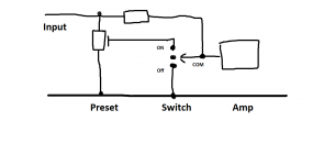
If you add a switch, then the switch must short the input of the receiver amplifier. If you leave the input open you will create a lot of noise in that room.
Com goes to the amp input/hot,
The On terminal goes to the source Hot, the Off terminal goes to audio return, i.e. the other half of the two wire feed to the receiving amplifier. There will be a momentary noise as the contact flicks over between the contacts.
You set it visually to 100%, or 50%, or 20%, or????
Linear works fine for this.
If you add a switch, then the switch must short the input of the receiver amplifier. If you leave the input open you will create a lot of noise in that room.
Com goes to the amp input/hot,
The On terminal goes to the source Hot, the Off terminal goes to audio return, i.e. the other half of the two wire feed to the receiving amplifier. There will be a momentary noise as the contact flicks over between the contacts.
I would agree with shorting the amp input as a means of muting as being the best option. Just simply switching to ground would be my solution for the most noise free option.
That does however raise the possibility (and its good practice to consider all scenarios) of a preset being on or near full setting. That would effectively short circuit the opamp output (which is a survivable condition as far as the opamp is concerned) but non the less something that should be avoided.
The addition of a series 2k4 or higher resistor in series with each preset would eliminate any issue. The downside is you lose a little signal. Would that matter ?
Well if the system didn't go loud enough (a bit unlikely) then its easy to add gain to the opamp to compensate.
Alternatively,I would agree with shorting the amp input as a means of muting as being the best option. Just simply switching to ground would be my solution for the most noise free option......................
The addition of a series 2k4 or higher resistor in series with each preset would eliminate any issue. ...................
still using the 2way 2pole switch. Com to receiver. trim wiper to ON and signal return to OFF. Connect a resistor of value ~two times the trim pot value from top of trimmer to Com.
This keeps the receiver Hot connected via the ~20k extra resistor to the signal when the moving contact is mid stroke.
When ON the extra resistor has almost no effect, it raises the output voltage slightly.
When OFF the extra resistor passes some signal to signal ground.
There may be a better way to locate this extra resistor. Any ideas?
Without the extra resistor the 47k Rin sees -6.47dB when trim is at 50%
With 20k extra resistor the 47k Rin sees -5.51dB when trim is at 50%.
That is an increase in senstivity of less than 1dB due to adding the resistor across the switch.
Last edited:
Had to think about that and draw it out.
Yes, that looks good as long as the receiver input doesn't ever see a momentary condition of the 20k to signal input. Or am I imagining it wrongly.
Yes, that looks good as long as the receiver input doesn't ever see a momentary condition of the 20k to signal input. Or am I imagining it wrongly.
If the signal input of the receiver still sees the 20k extra resistor (still connected to source) when the moving contact is mid stroke, the receiver is NOT seeing an open circuit and will only develop the noise of a 20k and almost no hum because the loop area in the input cabling is still small.
It's when the input has a very long interconnect that is open at the remote end that the receiver develops a lot of noise and often some hum. That's the condition that should be avoided when in the mute condition.
Maybe the added resistor needs to be a bit bigger. Maybe closer to the Rin of the receiver.
when the moving contact is midstroke, the 20k attenuates the signal by ~3dB.
Whereas if the added resistor is 47k the same as Rin the signal is attenuated by 6db during the switch over. That could be similar to the trim attenuation if the pot was set to ~50%.
There may be a better way of doing this.
Last edited:
- Status
- Not open for further replies.
- Home
- Source & Line
- Analog Line Level
- Volume Potentiometer Sizing and setup