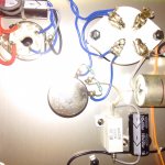
There is a volume control placed between the two big Pins power tube. Can I by pass it? What is the effect of turning it down (counter clockwise) and turning it up (clockwise) on the power tube it self? More or less power? Thank you for your help
Attachments
It is used to set the bias, do not touch it unless you know what you are doing.
[EDIT] Ignore the above, see post #5.
[EDIT] Ignore the above, see post #5.
Last edited:
Thank you for the information. O oh, I already changed it and I do not remember the correct or first set up. So the amp is not fixed bias obviously, isn't it?
This is not a volume control, but a humdinger pot.
It is used to minimize the hum when using ac to feed filaments/heaters.
What DHT are you using?
With low voltage types like the 45 and 2A3 you can get away with ac, higher voltage types like the 300B often are better off with regulated dc.
The minimum that you should do is properly twist the wires to the 'big pins'. The way it is now surely gives unnecessary high hum levels.
edit: read the sticky about heater wiring http://www.diyaudio.com/forums/tubes-valves/211731-heater-wiring-good-bad-ugly.html
Hi, thank you very much. I am using 2A3. When i turn down all the way the hum goes up and when i turn up all the way up the hum goes up as well. I found the lowest hum at 10 o clock. The bass seems a bit punchier and lower, is it safe? I do not remember the correct or original set up but it is more than 10 o clock.
Last edited:
BTW: beside reducing hum, what can the spec. be changed with adjusting that pot? Anyway to eliminate that pot and just using fixed resistor?
That pot should be standard equipment for any DHT with AC filaments and should include the two resistors attached to the wiper. There is no "up" or "down" since it is in parallel with the filament transformer. It should be left in place and adjusted for lowest hum.
Your amp is cathode biased: the 880r resistor is the cathode resistor.
Your amp is cathode biased: the 880r resistor is the cathode resistor.
Palustris, thank you. Stock tube is JJ 2a3-40, (rated at 10 watts), in order to change to standard 2a3 or mono plate for example, do I need to change this resistor? How to calculate it? Lower value or higher?
The amp is rated at 10W output?
The JJ is an uprated 2A3 version that can handle much higher power and voltage levels than a standard 2A3.
Normal 2A3s will burn up or arc over.
Within spec a 2A3 can put out less than 4W.
The JJ is an uprated 2A3 version that can handle much higher power and voltage levels than a standard 2A3.
Normal 2A3s will burn up or arc over.
Within spec a 2A3 can put out less than 4W.
Yes, it's rated at 10W output. Do you know what should I change in order to make it down to 4-5 watts?
Without schematic and measured voltages it is all guesswork, so keep in mind things could be different...
To get 10W (marketing talk for 8?) the voltage on the DHT should be pretty high. 400+
The datasheet of the 2A3 shows 250V for SE operation. Add the drop over the cathode resistor and you arrive to a little less than 300V.
My suggestions: use a good regulator board to drop the B+ from whatever it is to under 300.
There are plenty of people over here who know the 2A3 better than I and will tell you what voltage to aim for.
Next would be to change the cathode resistor. Check the datasheet and the people here.
Essential: improve the wiring and/or move to regulated dc on the filament.
On the other hand: why get rid of the JJ? I'm pretty happy with their 300B.
Last edited:
Why would you want to do so?Yes, it's rated at 10W output. Do you know what should I change in order to make it down to 4-5 watts?
I love JJ 2a3-40 too but I have some 2a3 tubes.
I want to try my RCA mono plate but I am afraid I will destroy these tubes without modifying or adjusting it first.
I want to try my RCA mono plate but I am afraid I will destroy these tubes without modifying or adjusting it first.
The JJ 2A3-40 is rated at 40W plate dissipation. If you are running the tube at standard 2A3 operating conditions (the 880r cathode resistor adds verisimilitude to the assumption) the plate dissipation will be about 11.5W. Output power will be about 2.5W. To know the actual operating conditions will require measuring the plate to cathode voltage and the voltage dropped across the cathode resistor. The JJ 2A3-40 is a monoplate tube and as good or better than any NOS tube I have tried.
- Status
- Not open for further replies.
- Home
- Amplifiers
- Tubes / Valves
- volume control by pass power tube