Hi, I'm hoping for a little advice as I'm a rookie at electronics. I'm building an amp (TPA3255 from 3E with PS: LRS-350-48) or at least I would be if the amp were to ever leave the port in China (virus time!!). In the mean time I'm building a chassis vintage style, as in I have a couple of old Bakelite meters and a chickenhead knob so thought it would be fun to make the whole thing look old - just my thing. It would be nice if I could get the meters to work with the amp so my question is does the diagram (excuse bad drawing) make sense? If so what size Shunt would I need (I can't work it out), given I'm running at 48v (maybe a little less 45v?) for the Ammeter? Would I need to add a resistor? Any help appreciated.
Attachments

....and
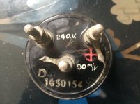
Forgot to add, the Ammeter says 240v so could it still work with 48v? Accuracy of meter is not important as it's just part of my fun? project.
Forgot to add, the Ammeter says 240v so could it still work with 48v? Accuracy of meter is not important as it's just part of my fun? project.
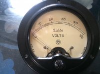
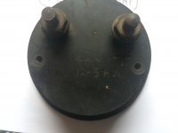
The voltmeter looks ready to go... try it on a 9 volt battery and make sure its OK. The 4ma/12.5k scratched on the back suggests it presents a load of around that value... so no problem there.
50 volts full scale and 4ma work out at 50/0.004 which is 12500
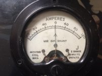
The ammeter has two options and you need the 90 millivolt one. What that really means is that the meter is a 90mv voltmeter in native form or a 240 volt meter with an internal resistor. A moving coil ammeter is simply a voltmeter with a shunt.
So that to me reads as two ranges, 90mv full scale and 240 volt full scale.
So you connect it across a shunt that will give 90 millivolt drop at the maximum current you want it to show at full scale.
So if that is 5 amps then you need a shunt of R=V/I which is 0.090/5 giving 0.018 ohms. Very low as it should be. Try a small piece of hookup wire a few cm long for that.
50 volts full scale and 4ma work out at 50/0.004 which is 12500
The ammeter has two options and you need the 90 millivolt one. What that really means is that the meter is a 90mv voltmeter in native form or a 240 volt meter with an internal resistor. A moving coil ammeter is simply a voltmeter with a shunt.
So that to me reads as two ranges, 90mv full scale and 240 volt full scale.
So you connect it across a shunt that will give 90 millivolt drop at the maximum current you want it to show at full scale.
So if that is 5 amps then you need a shunt of R=V/I which is 0.090/5 giving 0.018 ohms. Very low as it should be. Try a small piece of hookup wire a few cm long for that.
0.18 ohm is available ready made in 5W dissipation, check an electronic parts supplier.
Not sure about your drawing showing a grounded Ampere meter; proper use is connecting it "floating" (NO connection to ground) IN SERIES with +V wire, across the shunt resistor.
Not sure about your drawing showing a grounded Ampere meter; proper use is connecting it "floating" (NO connection to ground) IN SERIES with +V wire, across the shunt resistor.
0.18 ohm is available ready made in 5W dissipation, check an electronic parts supplier.
I think we wanted 10 times lower value than that... as a guesstimate of course if we are looking at say 5 amps max current.
And it all depends whether you want something accurately calibrated or just something that moves 🙂 We don't really know the max current draw of the amp either.
So perhaps make the shunt resistor higher in value so that you get decent volt drop at lower output levels and add a hotshot (lol, don't you just love spell checkers 😀) shottky high current diode across the resistor to stop any volt drop going to high. A clamp.
- Home
- Amplifiers
- Class D
- voltmeter and ammeter in circuit