So using tools like this to make sense of the valves load line https://www.vtadiy.com/loadline-calculators/loadline-calculator/
This seems to make sense for V1 as below
How do you work out the load for V2?
I will replace the coupling capacitors V1>V2 today and report back 🙂
This seems to make sense for V1 as below
How do you work out the load for V2?
I will replace the coupling capacitors V1>V2 today and report back 🙂
Attachments
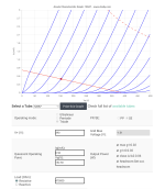
V2 has a special case where the load impedance "downstream" of the valve's own anode resistor is so high that it can be ignored - excellent! We need only mark two points on the axes and draw a straight line. Your posted curves are close but not exactly on classic American curves for 12AX7, plenty close enough, and the missing grid voltage curves' markings are in 0.5 VDC increments from zero (left).
Your operating "curve" (although we're drawing a straight line resistive approximation, the actual loadline is slightly elliptical because stray capacitance "fattens" the line, linearly variable with frequency; not a significant issue within the audio range in this particular case, but surprisingly significant in other cases) is a straight line from a point on the X axis at B+ (let's call it +378 VDC) and a point on the Y axis at +378 VDC / 301K Ohm (the anode DC load resistor). This is the current that would occur if the valve were able to conduct completely - a dead short. So, the reverse slope of this line is 301K Ohm.
As the voltage on the grid (blue lines) varies, anode voltage (on the red loadline) varies with it. 12AX7s are amazingly linear, so some amount of grid voltage change causes pretty much the same amount of anode voltage change at various places along the loadline, but there are definitely better and best places to operate.
If this is too simplistic, or not the actual thrust of your question, please restructure it and I'll try my best.
All good fortune,
Chris
Last edited:
I don't know how that program is working but tube load resistance is the plate rezistor in parallel with the grid resistor of the next stage
For V1 is 300K in parallel with 475K
For V2 is just 300K
For V1 is 300K in parallel with 475K
For V2 is just 300K


Well actually on further analysis and testing the culprit was actually a 0.082uF 400V Jensen PIO I had on as a bypass I had forgotten about on the other side of the PCB to replace the original bypass cap C40. Oh well, at least I am learning something!
So the Arizona caps are ok ? Could you maybe post specifics about which caps work, and which don't? This might be helpful for other people.
For sure.
I also tried these and they work too: Metalized Polyester Film DME Orange Drops [30v]
Jensen Aluminium Foil, Paper in Oil, in an Aluminium can: These leak DC in my case about 700 mV from 170V, which upsets all of the voltages across the valve. I tried both the 400V and 630V versions
Arizona Capacitors Blue Cactus : These work and 'leak only' 6-10 mV, this gets me the correct voltages across the valve as expected.
I also tried these and they work too: Metalized Polyester Film DME Orange Drops [30v]
well actually I just have, I had a friend around who likes music (play guitar, and his partner play piano) and he was intrigued by the 211 amplifier so we ended up playing some music and he said he had no idea you could get hifi to sound so much like live musicNow you can listen some good music 👍
DME orange drops are 630VFor sure.
Jensen Aluminium Foil, Paper in Oil, in an Aluminium can: These leak DC in my case about 700 mV from 170V, which upsets all of the voltages across the valve. I tried both the 400V and 630V versions
Arizona Capacitors Blue Cactus : These work and 'leak only' 6-10 mV, this gets me the correct voltages across the valve as expected.
I also tried these and they work too: Metalized Polyester Film DME Orange Drops [30v]
All of the Az-cap cactus parts should have an insulation resistance of 1.2x10^4 megohms at 500VOk, but they do need to meet the specs for this amp, which implicitly seem to be >2000 MegaOhm DC leakage resistance. Maybe ask Arizona Caps about that.
- Home
- Amplifiers
- Tubes / Valves
- voltages making no sense - help!