Chris,How are you measuring V2's anode voltage? Remember that it's at a very high impedance point and that your voltmeter probably loads that point significantly.
Semi-cons tend to fail catastrophically, usually to short, and tend to damage other connected semi-cons. Replace all of the semi-cons in that regulator. (Also any electrolytics if there were any). Parts are cheap and potential unsoldering/soldering damage to the board is more important than a few cheap parts - fix it once. You really don't care if it costs 5 or 50. Doesn't matter.
All good fortune,
Chris
I know you changed your advice to not rushing into swapping out the TL071, but a quick question on the possible culprits in the circuit, specifically D40K1.
I have got replacements for TL071, 1N914, Tip41, but D40K1 are hard to come by. ZD17 is already new and ZD14 measures 24V across.
So looking at the voltages here, do you think I need to get a D40K1 to try from some NOS supplier or is it already obvious I need to swap TL071?
Thanks for all the help,
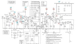
Viewing it from this perspective, and assuming that the red letter voltages are real enough (not automatically true because the measuring voltmeter effects measurements, but a good enough estimate at these fairly low impedances for our use), we see that the opamp has the correct 24VDC across its power supply pins 7 and 4, but that it has a voltage difference between its + and - input pins. Opamps are designed to try their hardest to keep that difference as small as possible by (external) feedback, which is (therefor) not in play presently.
To judge the reliability of our measurements, we can look at the direction that measured DC voltages would move with voltmeter loading. Pin 3 is a high impedance point, almost 100K, so will be dragged down more by loading than the lower impedance pin 2, connected directly to the followers' output (if they're working).
Then, we look at expected output DC voltage of the opamp. In this circuit the opamp is trying to make its output DCV as equal to pin 3's as it can, but it's failing to keep up. Measured voltage differences of a volt or a couple are simply not reliable for most DIYers, so we should ignore details around the followers. They may or may not have survived the failure event, but the best (only? secure course is to replace the opamp, followers, protection diodes and Zeners.
Does that procedure make sense, or have I skipped too many steps/assumptions?
All good fortune,
Chris

Semi-cons can be sorta/kinda tested with a common DVM, but everybody who plans to ever do any troubleshooting really, really needs a curve tracer. This is a widget with a 6.3VAC transformer to supply signal, a resistor (or two, switchable) and a viewing screen to display voltage (usually X) vs current (usually Y). Can be your scope, but any primitive ADC into a laptop can work. If not searchable, I'll try to draw, scan, post. But might be obvious from basic principles: 6.3VAC winding, resistor (about 1K Ohm), two test terminals, two scope terminals. Makes all troubleshooting mucho better and faster. Usable in-circuit with experience, or just good judgement.
All good fortune,
Chris
All good fortune,
Chris
Pins 2 and 3 , the opamp inputs , should be at the same voltage , this is how an opamp normally works .
D14 is good ? It is suspicious that has the same voltage on anode and cathode , normally it is reverse biased
Anyway if the whole regulator is dead it is logical that the output will allways be 398V - 24V( ZD14 ) - 0,7V ( D14) = 374V as those 2 diodes are an alternative path from input to output.
In fact for this regulator the minimum output voltage is 374V and can only be adjusted upwards
Last edited:
So with all things considered below 😉
1. This is a long term keeper preamp
2. I am capable of soldering, and being logical with help, but I don't have any test equipment outside of a DMM, and the occasional use of REW as an oscilloscope and spectrum analyser
3. I can source the remaining D40K1 as new old stock, and I have all of the other components.
So.....I think I am going to replace
Thanks!
1. This is a long term keeper preamp
2. I am capable of soldering, and being logical with help, but I don't have any test equipment outside of a DMM, and the occasional use of REW as an oscilloscope and spectrum analyser
3. I can source the remaining D40K1 as new old stock, and I have all of the other components.
So.....I think I am going to replace
- some of the ZD1-8, as ZdD1 and Zd2 seem to test a on the DMM a bit weirdly
- D14, Q5, Q7
- TL071 C
- and maybe ZD15, ZD16 as I have these too.
Thanks!
I don't have time to see where is Q5 or other parts that are not in the schematic above . For this regulator you have 1 opamp , 2 transistors , 2 zeners and 1 normal diode
If you replace them it should work 99,99% 🙂
I recomand to change them at once since one bad component can easily damage other good componets in this low voltage regulator floating on a high voltage
If you replace them it should work 99,99% 🙂
I recomand to change them at once since one bad component can easily damage other good componets in this low voltage regulator floating on a high voltage
Last edited:
Well,
Thanks so much for the advice
I managed to get some NOS D40K1 transistors and as recommended in the last post I swapped everything out and managed to get the circuit working properly. I now get the B+ into V1, V2 and V3 at 388V which is pretty close to the target 390V 🙂 so thanks. I took my time with the desoldering, and replacing of the op-amp and it went pretty well.
However the same illogical outcome remains on the voltages around V2.
V4, V5 and V6 are a very similar circuit and these pretty much match the expected voltages. V1 is pretty good, but V2 is on a different planet!
The red voltages were before I fixed the transistor/diode/op-amp regulator circuit and the blue voltages are what I have now after getting back to 388v for B+
Any ideas?
Attachments
what I can do is use a diode - the Mk1 circuit used a 1N914 from Grid to cathode on V2 to V3 so I can swap out the JFET on one channel, replace with a diode and see what that does 🙂 Apparently the JFETs are low noise. As it happened they are all new, as a previous (useless) service guy fitted the wrong specification ones, so I put in the right model
Hey can I just add a diode in parallel without taking the JFET out and see how that works, I will likely to spoil the JFET taking it out and they are hard to get hold of?
Because the possible issue with the FET is that it's leaky, you really can't leave it in circuit. But, you only need to remove one lead and can leave the other side dangling in place. You could even just snip a lead open and tack-solder it back together if it turns out to be innocent of the crime. Just never admit to it in court.
All good fortune,
Chris
All good fortune,
Chris
Semi-cons can be sorta/kinda tested with a common DVM, but everybody who plans to ever do any troubleshooting really, really needs a curve tracer.
All good fortune,
Chris
Ok so lead snipped on 3rd leg of FET, and soldered a 1N914 Diode in place.
Voltages virtually the same as before (and the same from left channel with FET, and right channel with diode)
hhhmmmmm so what else can it be?!?!
I have also measured the cathode resistors R8=39.8K and R6=1.49K
Something crazy is going on somewhere!!
Voltages virtually the same as before (and the same from left channel with FET, and right channel with diode)
hhhmmmmm so what else can it be?!?!
I have also measured the cathode resistors R8=39.8K and R6=1.49K
Something crazy is going on somewhere!!
Wait a minute, wait a minute, wait a minute. Do you have any actual symptoms from this small variation, measured with an unspecified voltmeter, in very unimportant DC voltages? Or is this a matter of worrying about nebulous specified-without-tolerances schematic specs? This circuit will work perfectly fine with the CD voltages posted, so what is the actual issue?
Chris
Chris
I guess to me it does not seem like a small variation - but what do I know!
110V compared to 150V
Also the Line stage is a VERY similar circuit and the voltages here all match the design, so I figured something is wrong?
Finally the phono is a LOT quieter than the line stage (CD vs Vinyl) and I had suspected this was to blame?
Thanks,
110V compared to 150V
Also the Line stage is a VERY similar circuit and the voltages here all match the design, so I figured something is wrong?
Finally the phono is a LOT quieter than the line stage (CD vs Vinyl) and I had suspected this was to blame?
Thanks,
So you swapped the tubes and is not V2 the issue ? Plate resistors 300K are in specs ?
The voltages should be virtually the same like in the line stage
The voltages should be virtually the same like in the line stage
Last edited:
- Home
- Amplifiers
- Tubes / Valves
- voltages making no sense - help!