Hello everyone,
A long while back I had a problem with an old ARC SP8 that had been 'repaired' badly and was not working properly. After some amazingly helpful support from everyone I was able to deduce that the problem in the line stage was the repair guy had swapped out FETs in the circuit for the wrong specification and they had failed. once replaced it all worked well apart from a small residual hum that is now fully resolved.
I was not using the phono stage at the time, and so had not gotten around to putting in the correct FETs in this circuit (the line stage and the phono stage are very similar circuits in layout and topology). However after replacing the incorrect FETs and doing some more rigorous measurement on the phono circuit it's clearly not working properly and I can't figure out what is going on as the voltages just don't make any sense?Any ideas?
Attachments
What is your AC line voltage? Seems to be 10% too low.
Maybe you can adjust the primary winding to 220VAC instead, if you are using the 240VAC line connection.
All internal voltages can easily vary by 5% or more, even with a perfect AC line.
Maybe you can adjust the primary winding to 220VAC instead, if you are using the 240VAC line connection.
All internal voltages can easily vary by 5% or more, even with a perfect AC line.
Last edited:
AC is 243 -246V
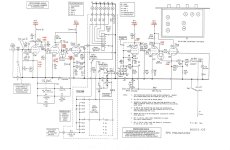
The conundrum is the voltage at the valve in comparison to that supplied to the anode resistor on V2, and of course the really large difference on V1.
V1, V2, V3 are the phono stage
The conundrum is the voltage at the valve in comparison to that supplied to the anode resistor on V2, and of course the really large difference on V1.
V1, V2, V3 are the phono stage
also ZD17 is strange, when I put a meter on either side of the diode I get the same voltage, and when I measure across the 100k resistor in parallel with the diode I see 1.2R
Then ZD17 is shorted and needs replacement. Verify this with out-of-circuit testing.
In one direction, it should test like a rectifier diode. The other direction should be open.
If it tests good, there is a different problem on the board.
That is an adequate good/bad test. It is a 20V, 1W 5% Zener diode. Do not substitute.
Be certain to replace in the same polarity as the original Zener diode.
Of course, DC voltages within the audio circuit will vary significantly
with different tubes. As long as the power supply DC voltages are nominal,
the remaining variation from the schematic is due to tube variations.
The high quality metal film resistors are unlikely to drift, and
the high quality film capacitors are unlikely to leak. Of course,
for various reasons there could be bad solder joints, etc.
Last edited:

Ok - thanks, I have some of these (https://uk.farnell.com/on-semicondu...v-do-41-2/dp/2453293?pf_custSiteRedirect=true) so these should match the specification I assume.
These measure in isolation 2MOhm across in the packet.
These measure in isolation 2MOhm across in the packet.
The input voltage is fine. You have 575 V in, 400 V out of the regulator. No big deal.
The main issue is with the regulator for 390 V (the opamp and surrounding components). I don't think ZD17 is fried. I think it's off on purpose during steady state operation. I bet its purpose in life is to charge C28 and C31 at startup to prevent the opamp from frying on startup. The main issue with the regulator is that its reference voltage (or set point) is off. The regulator is told to produce Vout = Vref = 398 V, which also happens to be the input voltage, so it never reaches the 390 V it's designed for. You'll want Vref = 390 V if you want Vout = 390 V.
Vref = Vin*(R59+R63)/(R59+R63+R60) -> Vref = 398*(2*1.82E6)/(2*1.82E6+100E3) -> Vref = 387 V.
You're seeing Vref = Vin, so the voltage divider formed by R59, R63, and R60 doesn't work. I bet one of the two 1.82 MΩ resistors has failed open. I'd replace both of them. It is possible that ZD17 has failed short circuit, but I'd check the resistors first.
It's concerning that the regulator isn't able to pull its output voltage up further than 374 V. This could be because D14 is fried.
If the output voltage of the opamp is near 400 V I'd suspect the two output transistors as well.
Tom
If the DC voltage across Zener ZD17 is zero during normal operation, it (or something else)
must be shorted across those two circuit nodes.
Normally there should be 11VDC across the Zener, which means that it is normally off.
must be shorted across those two circuit nodes.
Normally there should be 11VDC across the Zener, which means that it is normally off.
Ok - thanks, I have some of these (https://uk.farnell.com/on-semicondu...v-do-41-2/dp/2453293?pf_custSiteRedirect=true) so these should match the specification I assume. These measure in isolation 2MOhm across in the packet.
That will be fine.
In one direction, a good Zener should test as a regular diode. In the other direction, it should be open.
How does the Zener in question measure?
Not necessarily. The Vref node will charge to the full Vin through R60 if R59 or R63 is open.If the DC voltage across Zener ZD17 is zero during normal operation, it (or something else)
must be shorted across those two circuit nodes.
I don't know the TL071 well enough to say what will happen to its output if you take its non-inverting input all the way to its positive supply voltage as is the case here. If it does a phase reversal, like many opamps of its vintage do, and slams its output to VEE (Vout-24V) its current mode of operation makes perfect sense. I'd focus on getting Vref to 390 V.
Tom
OK > so I have dropped out the Zener Diode and in isolation out of circuit it is 1.2R so yes it's shorted.
Do you ever put diodes in parallel to share the current in case it was too much current making it over 1W?
I can just pop one new one back in, but it would be better if I can give it a little protection maybe? Just a thought
Do you ever put diodes in parallel to share the current in case it was too much current making it over 1W?
I can just pop one new one back in, but it would be better if I can give it a little protection maybe? Just a thought
Ok - new ZD fitted to match original specification no changes or 'good ideas' 😀
The drop across the diode is now 384 and 398 on the +ve side, so that's better, and seems to now be working as it should at this location.
Voltages on V2 anode still crazy low (102V and 91V) , supply into 300k is still 374V.
Voltages on V1 anode +165, + 190
It's V2 that is hard to understand, it's around 50V lower than expected??
I will measure the TL071CP pins and see if there are any errors or concerns about this next I guess.
However my simple logic says that is V2 is receiving 374V at the plate resistor which is confirmed to be 300K then why does it drop 50-60V lower than V1 (both 12AX7) and is the cathode bias voltage on V2 then a possible problem?
I just don't understand the V2 voltages, it's virtually the same set up as the line stage and this does not repeat the problem?
How do you measure it ? Input should be shorted so it is not amplifying the hum that would change the DC static voltages
B+ 374V vs 390V in shematic is not the issue here , probably the regulator is fine , anyway the important test is if it acually regulates the output when the load changes
That zener diode is just for protection , as I see the circuit , the voltage setting is done with the divider R60 100K and 2 x 1,82M in series
Not the actual output voltage is important but the ability to eliminate the AC hum
Last edited:
A quick question if it does not derail the purpose of this thread ... what is the role of that FET in this part of the circuit?

Thanks for your thoughts 🙂
I leave the mute on (so signal shorted)
agree 374V compared to 390V is not significant.
So the question remains, why does V2 drop so much voltage across the plate resistor? This I assume implies the current is higher through the anode resistor, but why / how?
I leave the mute on (so signal shorted)
agree 374V compared to 390V is not significant.
So the question remains, why does V2 drop so much voltage across the plate resistor? This I assume implies the current is higher through the anode resistor, but why / how?
I have checked the resistors on the cathodes and they are all correct.
The purpose of the FET is to act as a low noise diode in the configuration it is installed
The purpose of the FET is to act as a low noise diode in the configuration it is installed
Not sure if anyone has replied to that but no as their voltage is very likely to differ and they will share via their zener slope resistance 😉 fi they can. Better idea would be to just go for a higher wattage part same voltage. Doing that is unlikely to cause any harm.Do you ever put diodes in parallel to share the current in case it was too much current making it over 1W?
Without de JFET is the same ? 😁Thanks for your thoughts 🙂
I leave the mute on (so signal shorted)
agree 374V compared to 390V is not significant.
So the question remains, why does V2 drop so much voltage across the plate resistor? This I assume implies the current is higher through the anode resistor, but why / how?
If it is somehow leaky could explain why
- Home
- Amplifiers
- Tubes / Valves
- voltages making no sense - help!