Yes.Are you tested the CCS?
Without 6GK5 tube, appropriate resistor to ground.
What resistor are you referring to?
I can get small readings in millivolts (up to 500) between H&K when I energize them separately.Why would heater leakage current take a different path? Why would it never go through the CCS? The heaters are practically grounded, so sit at 0 Vdc. The CCS is being fed with -66 V. So if there any leakage between heater and cathode, why couldn't there be current flowing?
And why you resort to an ad hominem? It reminds me of this thread: 6C33C heater question
This happens as it's in the RC manuals.Perhaps heater to cathode leakage of a 6GK5 which only occurs when the heaters are working?
I've tried the center tap on the filament transformer grounded, not grounded and hooked up exactly as schematic with the same results.Are u sure it only drops when you plug in 6gk5 with only heater on and B+1 off? I'm surpprised the drop agreed with my sim with 6gk5 fully on.
I wish to expand bit if we're still on heater-cathode leak, when leak (after some heavy usage) occurs the voltage that destroyed the 330x resistors is coming from plate to cathode voltage of a few hundred volts. Not by 6.3v Ac.
So why not remove 330x2 resistor (only hum)?
But there is still a ground, ground with cap 0.1uf so to isolate any current.I've tried the center tap on the filament transformer grounded, not grounded and hooked up exactly as schematic with the same results.
What is the purpose of the 1 ohm 10 watt resistor? I didn't add that as I assume it's just a bleed resistor.
That is ground lift resistor. The electrical earth is connected to chassis and electrical ground of amp is connected to earth via a resistor so it's avoid pick up unwanted noise, hum, buzz etc below the difference of two ground potentials.


If the CCS set to -for example- 10mA (about 280R Rset), the test resistor 1k, so the voltage on test resistor is 10V.Yes.
What resistor are you referring to?
Bias is SET once the tube is HEATED up and B+ applied, not before the B+ and filament are stable.
Duh!
Duh!
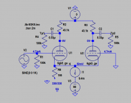
I didn't write that the problem was surely caused by heater to cathode leakage. What I did write is that it could be a possible explanation. There is a big difference between the two.This sim shows that CCS current flow in both grids when B+ is 0 or not connected, regardless of whether a heater leak or not.
So that is considered normal, there is no leakage after all.
In your post #18 you accused me of never proving a word I say. That is a flagrant lie. And if we only look at this thread, what was there to prove about me writing that heater to cathode leakage could be a possible explanation? Should I have mentioned literature in which this phenomenon is described to prove this possibility?
It is you who didn't prove anything that you wrote in your post #14. You started to use ad hominem arguments, starting in that same post # 14. I assume that it was caused by you being oversensitive for arguments that are not in line with your line of reasoning and/or me pointing out that you didn't get all that TS already wrote and showed (schematic in post #1) before.
About your simulation in post #30: What is the internal resistance of V2 in your simulation? If it is anything more than 0 Ohm, it would be impossible that the grid currents of U1 and U2 are of equal value.
A grid current of 4.7 mA at a voltage difference between cathode and grid of only 50 mV (with the cathode being positive with respect to the grid) seems unlikely to me. I know that grid current already starts from about -1.3 V (with the grid being negative with respect to the cathode) so I know that some grid current surely will flow. But could this grid current really be 4.7 mA at only 50 mV voltage difference?
My apologies to TS for this weird quarrel in your thread. It was my intention to try to help you but when I get attacked like this in public, I will defend myself in public.
I will quadruple check it a little later.Are you sure, that IXCP wiring is good, and tab shielded from "ground"?
View attachment 1095549 View attachment 1095551
If I wrote in details I afraid it would be off topic. If you really want an answer like you said you would rather than self defense, ask again nicely. No one is willing to do donkey work just to spoon feed anyone.I didn't write that the problem was surely caused by heater to cathode leakage. What I did write is that it could be a possible explanation. There is a big difference between the two.
In your post #18 you accused me of never proving a word I say. That is a flagrant lie. And if we only look at this thread, what was there to prove about me writing that heater to cathode leakage could be a possible explanation? Should I have mentioned literature in which this phenomenon is described to prove this possibility?
It is you who didn't prove anything that you wrote in your post #14. You started to use ad hominem arguments, starting in that same post # 14. I assume that it was caused by you being oversensitive for arguments that are not in line with your line of reasoning and/or me pointing out that you didn't get all that TS already wrote and showed (schematic in post #1) before.
About your simulation in post #30: What is the internal resistance of V2 in your simulation? If it is anything more than 0 Ohm, it would be impossible that the grid currents of U1 and U2 are of equal value.
A grid current of 4.7 mA at a voltage difference between cathode and grid of only 50 mV (with the cathode being positive with respect to the grid) seems unlikely to me. I know that grid current already starts from about -1.3 V (with the grid being negative with respect to the cathode) so I know that some grid current surely will flow. But could this grid current really be 4.7 mA at only 50 mV voltage difference?
My apologies to TS for this weird quarrel in your thread. It was my intention to try to help you but when I get attacked like this in public, I will defend myself in public.
Last edited:
Ok guys I apologize for being a bone head!Bias is SET once the tube is HEATED up and B+ applied, not before the B+ and filament are stable.
Duh!
Yesterday when I started ramping the B+ up the voltages looked real squirly and I quit increasing and started trouble shooting and notice the voltage fall when I added the heaters. Well I ramped up the variac to 122 volts line and Walla everything fell in place! I just started building **** with solid state in them and I'm not edumicated. Thanks for the help it is much appreciated.
OB
Member Kwadjo has been banned and allocated a random username.
Asking for an account to be disabled and then attempting to continue under a new registration is not acceptable and is against forum rules.
Asking for an account to be disabled and then attempting to continue under a new registration is not acceptable and is against forum rules.
Thanks, Koonw for the explanation.That is ground lift resistor. The electrical earth is connected to chassis and electrical ground of amp is connected to earth via a resistor so it's avoid pick up unwanted noise, hum, buzz etc below the difference of two ground potentials.
- Home
- Amplifiers
- Tubes / Valves
- Voltage falls off CCS/bias.