Hello!
Anyone has tried voltage doubler for big triode like 211 or 845 and operating around 1100v??
Any pros and cons with voltage doubler rather than conventional type high voltage with full wave rectification?
Thanks!
Anyone has tried voltage doubler for big triode like 211 or 845 and operating around 1100v??
Any pros and cons with voltage doubler rather than conventional type high voltage with full wave rectification?
Thanks!
The transformer will be considerably cheaper, and if you go with a quadrupler instead of a doubler, you could use a PT with a 230V secondary...
Here's an example using capacitors that are far too small. Ideally, you'd use HV diodes and 220u caps...
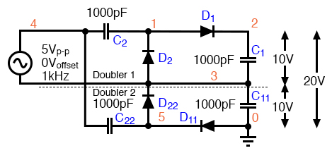
Here's an example using capacitors that are far too small. Ideally, you'd use HV diodes and 220u caps...
Well they need a lot of large capacitors and aren't very stiff.
Wikipedia article is quite useful Voltage multiplier - Wikipedia
Wikipedia article is quite useful Voltage multiplier - Wikipedia
With the AS-8T800 no voltage doubler is needed, just a rectifier + CLC filter. Lookks fine to me.
Regards,Gerrit
Regards,Gerrit
Well they need a lot of large capacitors and aren't very stiff.
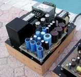
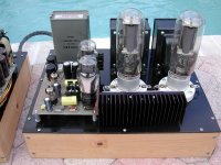
I built an 845 SE amp that used a voltage doubler made with 5AR4's running from a 480 to 120 volt industrial control transformer wired in reverse. It works, but I think that I would use a conventional rectifier circuit if I ever rebuild the amp.
I get a bit over 1150 volts with the output tubes cut off. It drops to 1050 with both channels at 75 mA, and 1000 volts at 100 mA. Silicon rectifiers would probably improve on this.
Attachments

The lower voltage power transformer is far easier to purchase and is less likely to be an obnoxious source of noise. Voltage doublers with solid state diodes have decent regulation. I did a ~1kV doubler power supply model versus a FWB power supply model with the same filter choke and similar capacitance, and the FWB supply drops about 5 more volts when stepping the load from 100 to 150mA. A big part of this is lower winding DCR in the HV winding. You don't care about this with a big class A SET amp though.Any pros
You have to keep a close eye on the AC current through the transformer. Doublers require a TON of AC current from the winding, which is not all that surprising all things considered. Yes, you will need big caps for the doubler itself, but this isn't as difficult as it once was to find appropriate caps.and cons with voltage doubler rather than conventional type high voltage with full wave rectification?
Last edited:
Contrary to common beliefs, voltage doublers aren't particularly disadvantageous compared to regular rectifiers; their main and only drawback is that they need more capacitors (but lower voltage).
This can be shown in a fair comparison, like this one:
Derating transformer for capacitive voltage doubler
This can be shown in a fair comparison, like this one:
Derating transformer for capacitive voltage doubler
Any drawbacks by using voltage doubler??
nothing if you design the thing well...
If doublers are so bad, why did Hegeman, McIntosh, Fisher, and Marantz use them? 😀
A SS "full wave" doubler working into a cap. stack, where each part is equal in value to the 1st cap. of of a SS full wave bridge's filter, will produce "identical" results.
Where the doubler can demonstrate an advantage is in the copper loss dept.
As was previously pointed out, implementation details are key, regardless of which topology is selected.
Attachments
Last edited:
for someone who makes traffos and chokes, the full wave bridge traffo is very easy on interwinding insulation and quicker to wind and is cheaper in the long run...
thicker wires are easier to make and costs cheaper than very thin wires for traffos...
thicker wires are easier to make and costs cheaper than very thin wires for traffos...
another big plus, is when running TV tubes with lower G2 voltages, you can tap the midpoint of the caps for half the voltage, then you need not use big and lossy power resistors to drop the voltage to say 150 vdc..
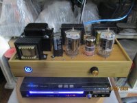
this is what i did to my recent all pentode single ended amp, 12gt5 and 6bn11 supplied about 150 vdc using a CCS depletion mosfets shunted by two 75volt zeners...
btw, all irons used in this amp was done by me...
this is what i did to my recent all pentode single ended amp, 12gt5 and 6bn11 supplied about 150 vdc using a CCS depletion mosfets shunted by two 75volt zeners...
btw, all irons used in this amp was done by me...
Attachments
Last edited:
With the AS-8T800 no voltage doubler is needed, just a rectifier + CLC filter. Lookks fine to me.
Regards,Gerrit
Or use the AN-4T400 with the windings in series and have a convenient 1/2b+ rail for the preamp or what have you.
- Home
- Amplifiers
- Tubes / Valves
- Voltage Doubler Power Supply for high voltage Big Triode??