Yes that's correct. If you apply a variable DC bias you can even watch the distortion blend from H3 to H2.It probably becomes predominantly second order when you have a large DC bias voltage across the resistor.
Resistor distortion is generally only detectable in carbon comp and (to a lesser extent) carbon film resistors operating close to their power limit. It's substantially absent from metal film and of course WW resistors.
+1I got more distortion out of the circuit with the better resistor. All I can figure was that the 2nd harmonic distortion generated by the thick film resistor was in opposite phase to the 2nd harmonic distortion of the circuit and was cancelling some of it. Improving a component doesn't always make the system better.
Very few people appreciate the power of distortion cancellation!
A quick ghetto test using what I had on hand. The two 1/8W carbon film (CF) resistors are the ones producing distortion in this setup, which rises at lower frequencies.
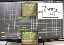
With no bias current they're both dissipating 50mW. The oscillogram shows the signal (1kHz) and the distortion residual, which is clean 3rd harmonic.
Cranking the bias voltage up to 40V results in 90mW dissipation in each of them. The overall distortion rises and is now dominated by 2H.
With no bias current they're both dissipating 50mW. The oscillogram shows the signal (1kHz) and the distortion residual, which is clean 3rd harmonic.
Cranking the bias voltage up to 40V results in 90mW dissipation in each of them. The overall distortion rises and is now dominated by 2H.
Attachments
Last edited: