Voice coil replacement on vintage Wharfedale 12" with step by step pics
I recently got given a pair of 12" Wharfedale vintage drivers, both with blown voice coils, so I thought I would post pictures of each step in the process of voice coil replacement. I carry out a lot of repairs on speakers, so will make similar threads for different repairs. (If this is in the wrong section feel free to move it to the correct location).
PLEASE NOTE: This is written only as an explanation to the process, and to give some helpful advice to those wishing to try it themselves. It is not a comprehensive how-to guide, and I accept no responsibility for and damage or injury resulting from this article. If anyone has any questions, I will be more than willing to help where I can
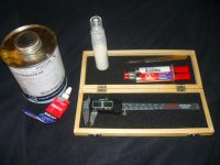
First up are the basic tools you will need: Scalpel, solvent and eyedropper, adhesive and some vernier calipers. I use toluene for the solvent, as it quickly softens most glues (not epoxy though) and doesnt harm most speaker materials. Please note it is not suitable on some types of plastic or foam surrounds, in that case a heated knife is a safer option.
Calipers are essential for accurate measurement of the voice coil dimensions for when you buy your replacement. The important dimensions are former height, winding height, overall thickness, and inside diameter.
The scalpel must be sharp and it is used for slicing through adhesive and separating different components.
I use Araldite for securing the coil to the cone and spider. I use Ados or similar for gluing the spider to the basket, as well as rubber surrounds. For dustcaps and foam surrounds, I use a white PVA based adhesive, which is similar to wood glue but more tacky.
I recently got given a pair of 12" Wharfedale vintage drivers, both with blown voice coils, so I thought I would post pictures of each step in the process of voice coil replacement. I carry out a lot of repairs on speakers, so will make similar threads for different repairs. (If this is in the wrong section feel free to move it to the correct location).
PLEASE NOTE: This is written only as an explanation to the process, and to give some helpful advice to those wishing to try it themselves. It is not a comprehensive how-to guide, and I accept no responsibility for and damage or injury resulting from this article. If anyone has any questions, I will be more than willing to help where I can
First up are the basic tools you will need: Scalpel, solvent and eyedropper, adhesive and some vernier calipers. I use toluene for the solvent, as it quickly softens most glues (not epoxy though) and doesnt harm most speaker materials. Please note it is not suitable on some types of plastic or foam surrounds, in that case a heated knife is a safer option.
Calipers are essential for accurate measurement of the voice coil dimensions for when you buy your replacement. The important dimensions are former height, winding height, overall thickness, and inside diameter.
The scalpel must be sharp and it is used for slicing through adhesive and separating different components.
I use Araldite for securing the coil to the cone and spider. I use Ados or similar for gluing the spider to the basket, as well as rubber surrounds. For dustcaps and foam surrounds, I use a white PVA based adhesive, which is similar to wood glue but more tacky.
Attachments
Last edited:
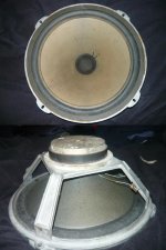
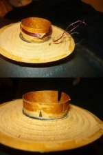
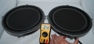
Here is a photo of the driver in question. Has no model numbers, just says "Wharfedale, England". The have a very light cone, thin rubber surround, and an aluminium damping ring attached to the cone beneath the dustcap. This is to add mass, and I imagine to raise the drivers Q. From looking at the driver they would have been in a sealed cabinet.
Attachments
The first step is to remove the speakers software, ie. the cone, surround, and spider. To do this, I apply a small amount of toluene to the edge of the spider where it is glued. And depending on the type of surround, I either apply toluene to that too, or carefully cut the adhesive holding it to the frame with a scalpel using a curved blade. Care must be taken not to slip and slice through the surround or your own hand.
Another option is to use a heated blade, this works better with delicate surrounds such as foam as it slices through the adhesive but doesnt damage the surround if you work quickly and efficiently.
Once the adhesive is softened, you can work the scalpel between it and gently prise it upwards, and you can use the back edge of the blade or a blunt butter knife to help separate the surround or spider from the basket.
Attachments
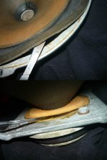
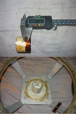
After that you remove the dustcap, and remove the cone assembly from the basket. To remove the dustcap on some drivers you can apply a few drops of toluene around the egde and remove it intact, but I prefer to carfefully cut around the edge as otherwise you can tear the cone.
Use a scalpel blade that is straight and has a sharp tip. Then its simply a matter of de-soldering the two braided lead wires from the terminals and the cone should come out freely. If it doesnt want to come then dont force it, find what is sticking and gently free it.
In the upper pic you can see the aluminium damping ring glued to the inside of the coil.
Attachments
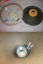
Now it comes time to inspect the voice coil and take the necessary dimensions. What you need to know is the height of the former, the height of the actual windings, the thickness of the windings, and the inside diameter of the coil. If any of these are not correct then the coil may not fit in the gap, or it may rub, or alter your X-max. Sometimes it is possible to deliberately use a different coil, for example if you want a longer X-max then fit a longer coil, but check the depth of the gap first or it may hit the back plate.
As you can see, this coil is well and truly busted. It is only on a paper former, and the adhesive had probably dried and perished over time.
After you have taken your measurements, carefully cut the coil free. I use the sharp straight blade, and go in from the front. In the second pic, note the scalpel blade, carefully work your way around the circumference of the coil. Better to go slowly and not slip and be accurate, than to rush and slice through the cone. The coil should slide out freely and leave a neat and tidy hole.
Attachments
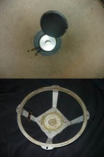
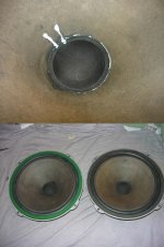
Here is a pic showing all the separated components: The cone/spider, the old faulty coil and its former, and the damping ring.
The damping ring could be omitted if one wanted to customise the driver and experiment, but I will be re-installing it to keep the drivers as close to original spec as possible. In this case I was able to keep the cone attached to the spider which is preferable, but not always possible. Always try to keep the hole as neat as possible and close fitting, as it will aid the centering of the assembly when it comes to re-assembling it.
This is all for now, until I source some new coils for the drivers. Then I will continue to update
Attachments

I have managed to find some replacement coils and am now just waiting for them to arrive.
On drivers of this age, the paper degrades and can lose strength. These ones were also starting to go a bit fluffy on the surface, as the glue holding the fibers deteriorates.
What I did was mix up some PVA wood glue and some water, to a consistency that was runny and easy to brush but still white. It doesnt take much water.
I just give both sides of the cone a liberal brushing, and let it soak into the cone. When it dries it restores strength and keeps it looking fresh.
In some places the rubber surround had just begun to start to split. I open the split up, and gently apply a small amount of ados and smear it with my finger,
this holds it together and it is barely noticeable from the front.
Now I just have to wait for the coils to arrive and then re-assemble. More photos to come!
Great thread flyingtele. Here's a link to a Snell Model A woofer's VC replacement thread.
Model A recone challenge - The Classic Speaker Pages Discussion Forums
Looking forward to the remainder of yours. IMO, alignment of the new coil in the old cone is the most difficult part so it doesn't rub afterwards.
Model A recone challenge - The Classic Speaker Pages Discussion Forums
Looking forward to the remainder of yours. IMO, alignment of the new coil in the old cone is the most difficult part so it doesn't rub afterwards.
Well the coils have arrived! The replacement coils are on a polyimide former, so these drivers will ow have a higher power rating as the previous coils were made from paper. Now the fun part, re-assembly.
The first thing I do is mark on the coil its correct height. There are various methods to do this, and it i essentially the same process as calculating the drivers X-max (linear excursion, for those that don't already know).
I measure the coil winding height, in this case its 10 mm. Then I measure the thickness of the top plate and subtract that value from the winding height. In this case it is 5 mm, so that leaves 5 mm. Then I divide that by two, to give the amount of winding overhang either side of the top plate, which will be 2.25 mm. I set my calipers as close as possible to 2.25 mm, in the photo it shows 2.27, but 0.02 mm will not make a difference.
I then put a piece of masking tape on the coil to mark where it should sit in the gap.
Next up is to find some shims of suitable thickness that can firmly hold the coil in place, but loose enough not to distort the coil and allow adjustment. On these drivers, I found a pair of cardboard playing cards to do the job nicely.
Attachments
Once I find suitable shims I put them in the gap, and then place the coil in the gap. In the photo you can clearly see how the masking tape is used to set the correct height, by being in line with top plate. Once the coil is set, make sure the shims are right against the back plate of the magnet, and carefully draw around the top with a fine point Biro or felt pen, as this will help later when gluing the cone to the coil.
After that, I remove the tape from the coil and remove the coil from the gap. I then fit the coil to the inside of the cone. This is where it is important to be careful when removing the old coil from the cone and leave the hole as clean as possible. That makes it much easier to get an accurate fit when installing the new coil.
With the new coil sitting in the cone, I put the whole assembly back into the speaker basket, and then insert the shims. Now, I line the top of the coil up with the line that I drew on the shims to ensure correct height. This is visible in the second pic.
Once I am happy that the cone and coil are at the right height, and everything is nice and square, I apply four dabs of Araldite to hold the cone to the coil.
This is enough to hold it securely, but it means that there is very little glue to cut should something go wrong (and sometimes things do!). These vintage drivers have very tight clearances in the magnet, most probably to provide higher sensitivity for the lower powered amps of the day. One one of the two drivers I had to do this step twice before I was happy, but the second time was fine. But that proves why not to glue it all at once.
Once its set, I hold the spider in place with my hand and remove the shims. I then carefully manipulate the cone to test for rubbing. If I am satisfied, then I remove the whole assembly and apply Araldite all around the coil to secure it to the cone.
Attachments

Next step is to glue everything back together for good (hopefully!). I simply apply a layer of Ados to the magnet and surround flange on the basket, and do the same on the spider and suround.
When I install the cone, I put the shims into the gap first to provide a guide so that everything lines up at first contact, as Ados is a contact glue and when used properly, as soon as the surfaces touch, they are stuck.
These drivers have a recess where the surrounds fit in which helps to locate them, so I glue the surrounds down first. Then I carefully push the coil into the gap until the spider meets the magnet, and then just push down aroud the edge to make sure the spider is glued properly.
Now I leave it to sit for ten minutes or so, and with any sort of luck, it should all be perfectly centered.
I remove the shims gently and test for any rubbing, and if all is well I re-insert the shims and leave to cure overnight. If its rubbing, then I would start that step over again, as its easier to dismantle if the glue is not fully cured. And if its rubbing at that stage, its not going to fix itself by letting the glue cure.
But these drivers were fine and needed no such re-doing. After that, I glue in the aluminium damping ring, and solder the lead wires from the coil to the lead wires from the terminals and glue them down with either PVA or ados (PVA in this case) as well as re-soldering the lead wires back onto the terminals.
Attachments
After everthing is glued and soldered, the last step is to re-glue the dustcap. After a successful re-coil, this is like putting the icing on the cake
I just use Ados or PVA depending on the particular speaker.
Once its all dry, I then run a swept sine signal through it to check for any rubbing or buzzes or other problems etc. Both drivers checked out perfect.
After doing all that work and testing it, there is always a sense of self reward when listening to music through the speaker, that a couple of days earlier was in bits and had it's new voice coil arrive in a box from the courier.
Below is a picture of the finished drivers, ready for action. The cones are bit darker since I gave them a light coating, but now have their strength restored, and are not fraying at the surface. One has green felt around the edge, the other has grey foam. I now plan to buy some green felt so that the other driver matches, and then think of something to use them for, but I plan to sell these on to someone who has a use for them.
So there you have it, step by step photos of a voice coil replacement
Attachments
Very nice job flyingtele.
Your's is a procedure one can follow if the old dust cap can be removed from the salvaged cone.
In the case of my VC replacement on a Snell Model A woofer, removal of the dust cap wasn't possible due to the addition of poured and cured resin around the dust cap.
So, within this one thread there are two ways described (yours directly and mine with a link) to replace voice coils in vintage cones.
Indeed, should be a good reference for others. Fun speakers to work on are the flat panel speaker such as certain Technics SB series woofers, as they dont have a dustcap at all lol.
Thank you!
That's an amazing how to.
I've got an old Wharfedale woofer with a VERY bad coil. Could you tell me where you were able to source your replacement VC?
My challenge is to get my cone out, without access to the dust cap. The woofer is from a W90, and has a foam (polystyrene) diaphragm glued into the cone. Pic below.
With the help from your post, I'll give it a try. I'll have to center it without shims, using a tone to the speaker. I guess I've got nothing to lose.
Attachments
Hi Flyingtele
I have a damaged voice coil in what looks like the same vintage 12in Wharfedale speaker.
Do you recall the dimensions of your replacement and where you sourced it?
I have a damaged voice coil in what looks like the same vintage 12in Wharfedale speaker.
Do you recall the dimensions of your replacement and where you sourced it?
The 12'' Wharfedale bass speaker in the old post from flyingtele appears to be from one of the Dovedale models that were manufactured from the late 1960,s. The bass unit used a 1.5'' diam. voice coil and I believe later versions utilised a 2'' diam V.C. for improved power handling capacity. The rubber roll surrounds have a habit of hardening with time and this can cause the cone to crease. Speakerbits in Port Melbourne may have a supply of suitable replacement coils.
Last edited:
Some decades ago when I was a "poor" apprentice I used to directly rewind voice coils on the existing formers (still attached to the cone). The process needed some patience and a matching cylindrical support in order to avoid collapsing of the voice coil former while winding.
Regards
Charles
Regards
Charles
- Status
- Not open for further replies.
- Home
- Loudspeakers
- Multi-Way
- Voice coil replacement on vintage Wharfedale 12"