Apple version is not available. You can use Boot Camp to install Windows, but I don't know how .NET apps work.
🙁🙁🙁🙁
@ kimmosto
If you could include an Optimizer at some point, i would be Highly delighted & find it Extremely useful. As i'm sure lots of other people would too 🙂
Please put it on your list of to do's, if you can 😉
If you could include an Optimizer at some point, i would be Highly delighted & find it Extremely useful. As i'm sure lots of other people would too 🙂
Please put it on your list of to do's, if you can 😉
Revision 1.1.8.0 (2017-06-22) is out.
See changelog, refresh to see the latest.
Thanks for adding filter response in enclosure tool! You are the best 🙂
If I remember correctly, having only Sd, Mms, Cms, Rms, Re and Bl parameters you can calculate all the rest of T-S parameters. These are fundamental properities of driver along with Xmax and Prms and Vbox they allow to calculate boxes transfer functions. You could allow calculations not only from Qes, Qms, fs, Vas side but also from Sd, Mms, etc. side as well.
Last edited:
If I remember correctly, having only Sd, Mms, Cms, Rms, Re and Bl parameters you can calculate all the rest of T-S parameters.
User must enter Re, fs, Qms, Qes, Vas, Sd and Xmax to VCAD. Manufacturers usually know and inform these. Program is able to calculate Qts, Cms, Mms, BL and Rms if not entered by user.
Last edited:
Capacitor Tuning
Enclosure tool can use crossover in main program. No problem to tweak with single cap or full crossover - passive or active.
Enclosure tool can use crossover in main program.
How to do it?
How to do it?
I can not use this for a speaker from a database.
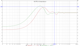
Start Enclosure tool. Select driver from database and radiator type (closed). Export Impedance response to text file.
Activate main program window. Select exported impedance response for driver (Driver 1, Way 1). Add 1000uF capacitor to crossover.
Return to Enclosure tool window and check "Crossover of current driver" in Align tab.
Tweak capacitor value in crossover and look total response in Enclosure tool.
would be fine if you add this procedure in the manual
Linking from crossover to Enclosure tool is already mentioned in manual. No plan and time to copy everything to procedures and check lists. Sorry that user have to play and study to find out different ways to use the program.
Another procedure option using Feed speaker:
Start Enclosure tool. Select driver from database and radiator type (closed). Check Feed speaker. Export Impedance response to text file.
Activate main program window. Add 1000uF capacitor to crossover.
Return to Enclosure tool window and check Crossover of current driver in Align tab.
Tweak capacitor value in crossover and look total response in Enclosure tool.
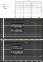
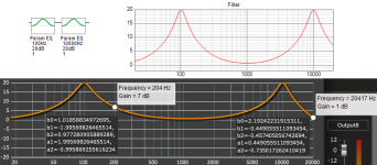
Warning about biquad coefficient copy/export. VituixCAD calculates coefficients according Excel sheet by miniDSP: All_digital_coefs_v1-20101026.zip.
That is based on bilinear transform (BLT). One problem with the BLT is frequency warping towards the Nyquist frequency. For a low-pass filter with a resonant peak the result is too steep falloff for high cut-off frequencies. Similar effects are present for other standard filter types.
Frequency response of DSP device could be different than ideal (analog) response shown in VituixCAD.
Few examples attached.
Attachments
Diffraction model
Hello Kimmo. Firstly thank you for excellent software.
I have some question. I tried modeling front baffle in diffraction application and I compared it with other software. I have found little differences, data in both, of course, the same. I attach an image.
Hello Kimmo. Firstly thank you for excellent software.
I have some question. I tried modeling front baffle in diffraction application and I compared it with other software. I have found little differences, data in both, of course, the same. I attach an image.
Attachments
^Different level at low frequencies is related to listening/mic distance. VituixCAD calculates to axial distance entered by user. Maximum baffle loss is less than 6 dB if distance is "normal" 2.5...3 m. You can get closer to 6 dB by entering 99999 mm to axial distance. Most of the other simulators I've tested calculate baffle loss to infinity distance regardless of entered axial distance.
Other differences cannot be explained for sure without knowing how other programs calculate. I can just guess that Excel simulator does not calculate phase response of radiator before diffraction. That probably shifts peak to higher frequency.
Generally, I don't know any accurate simulator. Diffraction process is very very complex. Simulation algorithms are usually very simple compared to real life. For example VituixCAD calculates only first order diffractions (radiator->edge->listening point) with ray theory. That gives too shallow baffle step.
Thank you for answer, i try FRD Response Blender.^Different level at low frequencies is related to listening/mic distance. VituixCAD calculates to axial distance entered by user. Maximum baffle loss is less than 6 dB if distance is "normal" 2.5...3 m. You can get closer to 6 dB by entering 99999 mm to axial distance. Most of the other simulators I've tested calculate baffle loss to infinity distance regardless of entered axial distance.
Other differences cannot be explained for sure without knowing how other programs calculate. I can just guess that Excel simulator does not calculate phase response of radiator before diffraction. That probably shifts peak to higher frequency.
Generally, I don't know any accurate simulator. Diffraction process is very very complex. Simulation algorithms are usually very simple compared to real life. For example VituixCAD calculates only first order diffractions (radiator->edge->listening point) with ray theory. That gives too shallow baffle step.
i try FRD Response Blender.
That is very basic simulator for axial responses. Worth to stay in VituixCAD Diffraction & Merger tools due to off-axis and multi-driver and rectangle driver simulation, and merging of off-axis responses at the same time.
Last edited:
- Home
- Design & Build
- Software Tools
- VituixCAD