Hi Kimmo,
I know that you are not a big fan of Optimizers but they can be very helpful sometimes and yours works well. I was wondering if you might be able/willing/interested in expanding yours to work with a system target while specifying individual driver restrictions. I may be wrong but it seems as though VituixCAD currently tries to bring one driver towards the target at once even if components from both drivers are checked.
As always, thanks so much for your consideration of this request,
Jay
^Jay, are you optimizing listening axis only, or combination of listening axis and power response including 0-90/180 deg off-axis measurements?
Hi Kimmo,
I was referring to the listening axis but now that you mention it (as I certain compare my designs regarding the power responses, as well), I am thinking that I could deselect the off axis measurements and use the power response to do this; it would work if I leave out the frequencies where the HF driver starts to dip, just a little more tedious.
Again, thanks so much for this wonderful piece of work.
Jay
I could deselect the off axis measurements and use the power response to do this; it would work if I leave out the frequencies where the HF driver starts to dip...
This is something I would not do. Optimizer needs full off-axis and valid listening axis data to calculate as accurate combination of axial and power responses as data and simplified calculation method by two planes enables.
Purpose of my question was only to ensure that both axial and power responses are included with some balanced weighting 40/60%...60/40%. By single response - either weighting of axial=100% or power=100% optimizer is not willing to make compromises. It just makes everything - possibly stupid decisions to satisfy that single and narrow goal.
Optimizer scans components in "some order" testing new values first to the beginning of internal component list. That may lead to local minimum which is not the best.
Safest way to control and prevent bad optimizing decisions is just deselect parameters (optimize off) which you want to keep constant. Do not optimize too many parameters at a time.
Last edited:
A couple of questions:
Listening window is a nice feature, but...
i would like to have it a bit more flexible
in options:
Listening win hor "new box where you can define "center frequency(0 per default, to get current functionality)" +-"The current box".
so you can define a listening window for 25dgr +- 15dgr for instance.
SPL directivity, why not 50db or user defineable?
Frequency axis: why cant i define 1000-20000Hz, 400Hz is the highest?
In Crossover tab:
a switch function like in lspcad would be really good, to be able to evaluate different solutions more quickly.
I'm going to ask again, it would be a really nice feature i you could press the visible checkbox and if unchecked it makes the fr not visible but is included in the power graph
extreme angles just clutters and makes it harder to see the separate angles. nice feature if you want to present a design.
or just to have some preferred angles in that window.
Keep up the good work Kimmo!
This is something I would not do. Optimizer needs full off-axis and valid listening axis data to calculate as accurate combination of axial and power responses as data and simplified calculation method by two planes enables.
Purpose of my question was only to ensure that both axial and power responses are included with some balanced weighting 40/60%...60/40%. By single response - either weighting of axial=100% or power=100% optimizer is not willing to make compromises. It just makes everything - possibly stupid decisions to satisfy that single and narrow goal.
Optimizer scans components in "some order" testing new values first to the beginning of internal component list. That may lead to local minimum which is not the best.
Safest way to control and prevent bad optimizing decisions is just deselect parameters (optimize off) which you want to keep constant. Do not optimize too many parameters at a time.
Thanks Kimmo. I was thinking along the lines of eyeballing the power while adjusting the axial response. Sometimes in Soundeasy, I will play with just a cap on one driver and maybe an inductor or resistor on the other and I find that with some designs, I get to where I want to get more quickly.
I really appreciate your work.
Jay
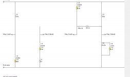
^That is from XMachina. You can draw that to VituixCAD or XSim exactly how it is in original.
An externally hosted image should be here but it was not working when we last tested it.
Soundeasy, I will play with just a cap on one driver and maybe an inductor or resistor on the other and I find that with some designs, I get to where I want to get more quickly.
That is exactly what I meant. Complete constraint system might be nice in theory, but could be too complex for majority - also for author himself 🙂 For example if you have 30 drivers in a project, you should be able to create separate constraints for all of those, or create driver groups (usually called as "ways") having common constraints. As we know, VituixCAD 2 does not have traditional ways other than output of active buffer/amplifier to show impedance curve of each driver group or semi-active way.
Adequate function could be much easier, just by toggling optimize status of two components/parameter groups with Optimize Toggle command in context menu.
A couple of questions:...
All of those would be doable, but significance might be questionable.
For example by rotating listening window is not so easy to get much different result than with existing zero centered. You need to rotate quite much to get rid of 0 deg. After that I will ask you all, why 0 deg is so irrelevant for speaker design that it needs weighting of 0% instead of e.g. 14% with +/-30 deg window (angle step 10 deg)?
Listening window average is not very significant in practice. Vertical plane with common multi-way is able to do something which is useful to take into account while designing sound balance, though 5 deg off-axis angle step is desirable to avoid exaggeration. It just appears "too" significant as long as full/half off-axis response set with power simulation is not available.
Same story with 400 Hz high limit and 1000 Hz low limit for frequency scale. Is 400...1000 Hz really so intolerable and irrelevant for speaker design that it should be hidden?
50 dB magnitude span is asked at least once a year. This is easy. 50 dB with 10 dB major grid will destroy scaling of phase axis: no 0 deg line at all, and major step would be 36/72 deg. 40 and 60 dB are much better and show everything what 50 dB can offer. You can test this with Calculator tool having quite free Y span setting.
Directivity chart has chart types such as polarmap, polar chart and surface chart which do not mix different off-axis angles into flat mess. Separate toolbox window to show/hide individual directions in Line and Area charts would be doable, but clicking of max possible 180 curves on/off might not be so motivating compared to highlighting with reference angle selection or selecting some other chart type.
Scenario menu would also be doable and easier/faster than saving most promising intermediate results to project file. XML structure of project file would need some redesigning to support also saving of scenarios for the next session. This would be easy to do as a run-time feature by using same functions with Undo, but users won't be happy if scenarios are lost when project is opened next time.
Last edited:
^That is from XMachina. You can draw that to VituixCAD or XSim exactly how it is in original.
An externally hosted image should be here but it was not working when we last tested it.
Sorry, wrong thread, I was tired last night, but thank you!
David.
That is exactly what I meant. Complete constraint system might be nice in theory, but could be too complex for majority - also for author himself 🙂 For example if you have 30 drivers in a project, you should be able to create separate constraints for all of those, or create driver groups (usually called as "ways") having common constraints. As we know, VituixCAD 2 does not have traditional ways other than output of active buffer/amplifier to show impedance curve of each driver group or semi-active way.
Adequate function could be much easier, just by toggling optimize status of two components/parameter groups with Optimize Toggle command in context menu.
Understood. Thanks for the explanation Kimmo. Jay
a switch function like in lspcad would be really good, to be able to evaluate different solutions more quickly.
I have done quite serious test with this. It's nice programming challenge and useful feature, though saved intermediate results in different program window work too.

Main setback is that undo buffer is better to reset when scenario is changed with recall button (R1...R5). Otherwise might happen something nasty. I don't like to add individual undo buffer for all five XO scenarios.
All scenarios are saved to project file so work won't be lost.
Here it is. Backup project before overwriting vxp, or save as...
Rev. 2.0.7.0 (2018-11-26)
* Added Scenario menu to Crossover tab. Visible schematic can be saved with store button S1…S5, and recalled with R1…R5 button. Stored scenario can be deleted by pressing Ctrl key while clicking recall button. Crossover versions are saved to project file (.vxp) for the next session. #1 is compatible with older project file versions of VituixCAD 2.0. Warning! Undo buffer is cleared when scenario is changed with S/R button.
* Added possibility to copy exported schematic and chart images also to clipboard.
Hi,
just to say thank you to Kimmo for this software, I'm not skilled in design loudspeaker, I have merely modified some crossovers in the past to meet my audio "taste". I'm reading this thread, and once finished I maybe post some questions or notes.
I've played with VituixCad for a week, maybe it would be nice to have some more flexibility with overlays. For example in Enclosure tool, the possibility to keep the overlay of driver X when you switch to driver Y, so that you can compare responses, as it is in Winisd. Or in the main window, to be able to visualize, or not, some driver's overlays (the mid, or the wf or tw... I do it just disconnecting the crossover) and choose the color of their overlays.
... keep practicing and reading 🙂
Thank you Kimmo !
Last edited:
^Enclosure tool has an overlay in SPL and Impedance charts, but database filtering features should reduce need of overlays. Set T/S and Select criteria and you can compare drivers by scrolling up/down, with or without 'Auto align' checked. Wouldn't be a problem to make another winisd, but that was not my vision.
Frequency axis: why cant i define 1000-20000Hz, 400Hz is the highest?
Limits are now changed in rev 2.0.7.1.
...makes the fr not visible but is included in the power graph extreme angles just clutters and makes it harder to see the separate angles.
Added 'Half space' option to context menu. Shows -90...+90 deg in Line and Area charts only. Hopefully this helps, though main target is to prevent mess and blocking with open baffle speakers.
Hi Kimmo,
A couple of requests that I think are pretty minor.
Any chance that you might add the option to the File->Export command to choose .txt or .frd for all of the options?
Any chance that you might add an option for where to save and with what extension (.txt or .frd) for the Tools menu at least under the Merge tool?
Though I am now using primarily your tool, sometimes (like at work), I can only use excel based programs like PCD, which only takes the frd extension.
Thanks so much for your consideration of this request.
Jay
Hello
Recently downloaded to give this a shot. I like what I see in terms of functionality, and it's all good.
However I have two observations after my first few attempts at using the software:
1. Many driver datasheets will come with minimum Z at zero ohms. The SPL tracer does not work with a zero value. Any solution? I have used a grid to lay out a 5 ohm starting point, but it is not accurate enough.
2. I would like to understand the function of the SPL spec in the driver window, does this override the values set in the .frd file? Reason I ask is when I tried to use the traced frd file in a design, it defaulted to 80dB instead of the 89dB as it should. Other design software is reading the value correctly and correlating well with datasheet, so the frequency tracing is working correctly.
Thanks for any input you can provide.
- Home
- Design & Build
- Software Tools
- VituixCAD