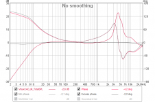
After the new update, I have an accurate coverage of the crossover and phase simulation with measurement. My calibration microphone file does not have phase information.
When measuring to the crossover, it always performs a reference measurement (midwoofer + tweeter), which is later added as Reference angle overlay (a bit of a pity that there is no option to scale this measurement). The measurement is done on the tweeter axis and this microphone position does not change.
Next, I enter the XYZ geometric data for the woofer and simulates the measurement distance of the microphone the same as for the measurement distance.
This simple method always gives me the maximum simulation compatibility with the measurement.
^^Ok.
I just did few small improvements to IR window, Z model and SPL Trace. The latest setup built is 2018-10-27 16:11 (UTC+2).
I just did few small improvements to IR window, Z model and SPL Trace. The latest setup built is 2018-10-27 16:11 (UTC+2).
After the new update, I have an accurate coverage of the crossover
As DB already explained, status of new Minimum phase checkbox does not change phase matching between woofer and tweeter if both IR measurements are time locked dual channel and converted to frequency responses with the same method (software and settings) - as they should be.
I will save Minimum phase checkbox this time for compatibility with programs which don't use phase column or calculate minimum phase by magnitude to get more accurate phase result. Usually this kind of additions are not very welcome because complexity and risk of wrong use increase.
...IFFT with file exports is in View->Impulse response window. Source response could be either total SPL, driver's SPL or driver's filter transfer function...
Had VituixCAD2 installed and feeded it some more or less complicated txt file response which belongs a calibration file for a headphone EARS unit from miniDSP and got it to output below 64bit stereo IR analyzed for minimum and excess phase into REW, that is fast and great result and can see many use cases where one in fast way can use it for model predictions and manipulation including how a factory datasheet curve probably will sound like if we load that IR into a convolution engine on a linear dialed in system, looks if txt response file have limited numbers at stopbands one have to manual way manipulate those tails in txt file but this feature is still very usefull and fast way, great thanks for guide.
Attachments
Last edited:
...looks if txt response file have limited numbers at stopbands one have to manual way manipulate those tails in txt file...
After some learning curve and practice time it works much better now, file is first put through calgulator feature "Minimum phase A" from there whatever weird response curve looks gets a pretty good quality export as IR 🙂
looks if txt response file have limited numbers at stopbands one have to manual way manipulate those tails in txt
Automatic slope detection is by the first and last 1/2 octaves. That works usually okay but not always.
Rev. 2.0.5.5 (2018-10-28) has manual adjustment of response tails in Minimum phase function of Calculator tool.
Impressed here and thanks those new v2.0.5.5 tail settings that makes up for fantastic flexibility.
Don't know if its a minor bug but "Higher tail" "dB/oct" wont take any positive numbers other than a zero, easy workaround seems set a minus in front of number and it works perfect.
Don't know if its a minor bug but "Higher tail" "dB/oct" wont take any positive numbers other than a zero, easy workaround seems set a minus in front of number and it works perfect.
"Higher tail" "dB/oct" wont take any positive numbers other than a zero
It was intended limit but I did forget that at least 6 dB/oct is possible in practice. Slope extends to infinity and endless increasing is not always possible.
Updated built has 6 dB/oct more in both ends.
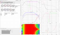
What a fantastic tool kimmosto, had me some exercise fun today and lets call it a virtual exercise because case is all based on predictions using real numbers for how i wanna rebuild that 2 way wall speaker seen out in avatar. To get directivity graphs i should probably had looked the suggested videos but this time i did it manual in 5º steps up at a time until 90º point using calculator tool and thereafter sat options to half space for this wall speaker. Directivity is full omni up to 3600Hz and far field real world above that point room sound is bit unatural dull so a gentle high shelve linear phase filter is used to lift that weakness caused using a 68mm diameter up so high in frq, but very flexible software package indeed so also added a 52mm piston into crossover section so as when one lift and move ground between that and the other 68mm piston one can get directivity comparison.
Do you think we can model and come close to real world for a line array with wall support using say 25 times TC9FD10-08 in a row.
Do you think we can model and come close to real world for a line array with wall support using say 25 times TC9FD10-08 in a row.
Attachments
Hi,
I have just installed the last available version. When I open the files from projects of the previous version I get the message (See the pic)
All of them are analog filters.
I have set the DSP in Options to Analog and saved the projects again to no avail
Is just a warning?
I´m doing something wrong?
BTW The projects open with no problem.
BR
Jose´
Attachments
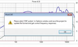
^It's a warning that project should be saved once with correct 'DSP system' selection in Options window to update older project file (vxp) format to the latest. After that nagging is gone and simulated frequency responses are compatible with selected DSP system.
Responses are already correct with analog projects because Analog is default selection in Options. Saving just stops nagging.
Responses are already correct with analog projects because Analog is default selection in Options. Saving just stops nagging.
Do you think we can model and come close to real world for a line array with wall support using say 25 times TC9FD10-08 in a row.
That is the goal, but you better use actual measurements of driver to 0-90 deg with steps of 5 deg to get much better directivity estimation than with ideal piston.
Merger tool is also able to merge simulated low to measured high, both far field. Requirement is that both have same angles e.g. 0-180 step 5 deg.
Quick question re Vituix measurement manual:
Does the tweeter need protection from low frequencies when measuring far field?
Does the tweeter need protection from low frequencies when measuring far field?
Does the tweeter need protection from low frequencies when measuring far field?
Depends on tweeter. I don't use protection for domes, compression drivers or (closed) AMTs.
Ribbon tweeters are more problematic. It's not so durable and load impedance is close to zero at low frequencies due to transformer. Amplifier may not like it. We have few choices:
1) High passing of measurement signal with measurement program. That is compensated automatically with dual or semi-dual channel measurement.
2) High passing of measurement signal with line level equalizer between sound card output and power amp. That is compensated automatically with dual channel measurement or semi-dual by connecting loop back signal from output of high passing device to reference input of sound card.
3) High passing of measurement signal with series capacitor (and optional resistor in parallel with driver) between power amp and driver. That is compensated automatically with full dual channel measurement by connecting loop back signal from driver's + terminal to reference input of sound card. Warning: power amplifiers in BTL connection need audio transformer for reference signal or reference signal can be connected from +terminal only to avoid explosion.
Few exceptions to previous:
All measurement programs do not have high passing for measurement signal. Logarithmic sweep itself is high passing for energy but not for amplitude.
All measurement programs or measurement modes are not able to compensate frequency response in dual channel measurement mode. Just timing. Support for response compensation should be tested before final measurements. For example REW, and ARTA with MLS and periodic noise might give uncompensated i.e. wrong result. I tested this few months ago but I don't remember exactly.
Thanks for your help.
So for a Nuub like me, a dome tweeter (such as my Revelator) should be fine with a full sweep without protection - assuming domes take the pain?
Does this mean the IR sweep should begin above a certain frequency, and how does one calculate that frequency?
So for a Nuub like me, a dome tweeter (such as my Revelator) should be fine with a full sweep without protection - assuming domes take the pain?
High passing of measurement signal with measurement program. That is compensated automatically with dual or semi-dual channel measurement.
Does this mean the IR sweep should begin above a certain frequency, and how does one calculate that frequency?
Last edited:
...a dome tweeter (such as my Revelator) should be fine with a full sweep without protection - assuming domes take the pain?
It can handle full sweep from 10 Hz but I wouldn't use more than about 2V signal.
Does this mean the IR sweep should begin above a certain frequency
No. High pass could be simple 1st order slope e.g. at 2 kHz. That is not very common feature in measurement programs. If I recall correctly, at least SoundEasy with MLS has it. MLS (without high pass) and periodic noise with white spectrum are quite safe for tweeters, though sine sweep is generally the best and should be selected for woofers and mids.
Starting sweep at driver's fs/2 is also one option with some programs but truncated responses might need some special processing with Calculator and Merger. VituixCAD extrapolates missing parts but automatic extrapolation is not so smart.
- Home
- Design & Build
- Software Tools
- VituixCAD