Since the horizontal polars are pretty close, I'll move to the next phase of analysis. Would you be comfortable with a ctc of 7.68" (195mm) for C, 8.46" (215mm) for D, and 9.25" (235mm) for E?
You should see the vertical change as you increase the CTC. You can change out the bottom right graph with a vert polar in the six-pack with some right-clicks in the graph.
CTC is the only change I'm making here, and yes the vertical response moves with it. I can generate rather decent vertical responses. Then the question becomes are there tradeoffs to large ctc distances? So I'm asking the question to the group: given a 6+1 (waveguided) speaker, what sort of ctc would concern you? None if the CTA2034 is ok? I thought I'd get more responses, this isn't a trick LOL
EDIT: ctc vs XO wavelength is 1.14x, 1.25x, and 1.37x for C,D, and E respectively.
EDIT: ctc vs XO wavelength is 1.14x, 1.25x, and 1.37x for C,D, and E respectively.
Not surprising as most popular think is that closer is always better, but in most practical constructions it's not.I thought I'd get more responses, this isn't a trick LOL
1.2 WL just between C and D seems about right for this combination, but the range of acceptable distances is pretty wide.EDIT: ctc vs XO wavelength is 1.14x, 1.25x, and 1.37x for C,D, and E respectively.
1.2 WL just between C and D seems about right for this combination, but the range of acceptable distances is pretty wide.
All my simulations (and now a real build) bear out the truth of this. I must say that 1.2xWL looks odd, but it does work. If you can't get the CTC spacing down to 1/3 WL or below, then 1.2 x WL may be the best compromise.
yeah, I was suggesting posting 6packs with the verts to show the difference. Plus look at the ceiling and floor reflection. Some folks look at where the XO nulls are pointed out to the room by bouncing them just before the LP.
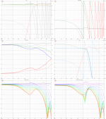
Just keep in mind your waveguide, the cone shape, and the dome shapes, will all mess with the sim. I had to move my tweeter up 75mm from where I expected it to go due to dome shapes vs the ideal sim.
My current XO is based on an ideal sim and has 1ft CTC. I arrived at the distance by looking at the verticals and on-axis. The sim says the sound power is even. Even with the 1ft CTC, I can stick my head 1ft from the tweeter and not be able to locate it- I just hear an even sound field.question becomes are there tradeoffs to large ctc distances?

Just keep in mind your waveguide, the cone shape, and the dome shapes, will all mess with the sim. I had to move my tweeter up 75mm from where I expected it to go due to dome shapes vs the ideal sim.
My question concerning what CTC you would be comfortable with comes from my experience with some speakers, where (usually) vocals wander between drivers, and I find it distracting. So those who have tried these higher 1.2x ctc haven't had issue with that?
If not, that was my last concern about the 1.2x idea. My other concerns have been largely removed, and, serendipitously, have dovetailed with two other concepts I've been thinking about in the last couple years.
My first concern was that as you move drivers apart, the main lobe becomes much smaller, and new lobes at the top and bottom appear and start to move in. Now, the narrowed main lobe is obviously happening, just look at the plots. No doubt the sweet spot is much narrower vertically. However, I don't mind designing around that, and at the end of the day, would always be willing to build a stand that puts the speaker at the appropriate height for the listener. But I think this requirement should be appreciated, especially if one is designing for retail.
What I did not expect, was the upper and lower lobes move inward quite quickly, and the nulls between lobes would be lessened. I like that. I also like that the ceiling and floor reflection are also smoother as a result and vertical DI higher. That's the first finding that dovetails with some of my thinking lately. I've become interested in wide and smooth horizontal response, but also constrained and smooth vertical response. My experience is that hard floors and the typical 8' ceiling really muck up the sound, and I wanted to remove it by constraining it to some degree, but also make it smooth so at least it blends with the horizontal sound well. The 1.2x ctc helps do that. A speaker that really showed this behavior is the Perlisten bookshelf speaker tested by Erin, and which is extremely well received critically.
The second finding that meshed with some recent thinking was that, if I were concerned about vocals wandering around, I could keep a close(r) ctc, but raise the crossover frequency and get the same vertical responses. Now this is often a problem, due to DI mismatch, but with a waveguide I realized it could work well. The ability to raise a crossover, or at least use a formerly common 2.5-3.0khz, is actually easier with a waveguide. Because of the "path dependence" of the use of waveguides in the DIY forums, I think we kind of missed this. As I recall the evolution of this thinking, oh 15 years ago now, was that people were wanting to push tweeters lower, so that the crossover could be placed before the woofer starts beaming. This of course puts a lot stress on the tweeter and it was recognized that a horn could relieve this stress. And ever since the focus has been to use a waveguide to push the crossover lower. All well and good and true - as far as it goes. But at the same time, the use of the waveguide alleviated the need to cross to the woofer below where it started to beam in the first place. Because the waveguide was also "beaming" at that frequency, and as long as the match was smooth, and in-room response a nice smooth slope - mission accomplished.
I think perhaps minimizing ctc was one reason thinking stayed in the particular lane it did for so long. But now that there is some proven benefit to wider ctc, I no longer have a reason to not use waveguide to match a woofer at a higher than expected frequency. The tweeter will like it much better, but more will be required of the woofer. Still, I don't think there is any longer an a priori prohibition against, say, a 2.7khz crossover on a TM, from a sound quality perspective. Thoughts?
Last edited:
While I have no opinion yet over the options what is better I really like what you write, questioning old habits and looking at things objectively. I remember you wrote critique on this large c-c some time ago due to smaller main lobe and I'm glad you have experimented over the stuff, found VituixCAD and gave the subject some thought. I suspect you have now put many many hours into it and I'm very positive that you will make better sound quality system just because of this new found open mindedness, no matter which c-c it is at the end that you end up using 🙂
edit.
I made some example some time ago to some thread that it is quite hard to get the nulls that are between lobes, at very low angles, to hit between ear and floor specular reflection (not to cause any harm) and relatively easy to fit between ceiling and ear (found it, it was on your waveguide thread 😀 https://www.diyaudio.com/community/...uides-for-cnc-3d-printing.318190/post-6990722
). For this reason try also take the listening situation under scrutiny, even if the DI is now better does a null still happen toward early specular reflection point and can you do something about it? This is perhaps mainly about height and tilt of the system, and listening distance.
Anyway, first reflections are very good place to optimize loudspeaker acoustic output, if at all possible. I havent experimented the stuff by listening yet but plan to. I'm kind of afraid to do listening tests due to perhaps very small differences and obvious bias since blind tests are cumbersome to arrange. Perhaps now at holiday season there is enough silent free time to do some critical listening for fun at least.
We have quite much data from simulations and its easy to make more, and try to reason over the stuff, but listening tests and reports are somewhat missing still. You could make freestanding waveguide so you can do listening tests without changing crossover. Or just few different baffle layouts to swap between.
Last edited:
And it might turn out that the c-c spacing just isn't as important as we thought it to be for various reasons, it could be this or that depending on what other aspects are optimized on any given system.
I think the best thing for now on the whole recent c-c discussion has been liberation from the tight c-c thinking. This enables more thought processes for designers and possible trajectories for loudspeaker system designs. For example freestanding axisymmetric waveguides, or any separate structures for drivers of multiway speakers for more separation of concerns, better utilization of system components to room height, easier manufacturing, all kinds of things for further optimized loudspeaker systems suddenly feel possible (altough they have always been). Perhaps we dont know yet what the best outcome of relaxed c-c spacing mentality eventually is. In addition we have great tools like VituixCAD. All this is very exciting, feels like progress 😀
I think the best thing for now on the whole recent c-c discussion has been liberation from the tight c-c thinking. This enables more thought processes for designers and possible trajectories for loudspeaker system designs. For example freestanding axisymmetric waveguides, or any separate structures for drivers of multiway speakers for more separation of concerns, better utilization of system components to room height, easier manufacturing, all kinds of things for further optimized loudspeaker systems suddenly feel possible (altough they have always been). Perhaps we dont know yet what the best outcome of relaxed c-c spacing mentality eventually is. In addition we have great tools like VituixCAD. All this is very exciting, feels like progress 😀
Last edited:
And it might turn out that the c-c spacing just isn't as important as we thought
Ah yes, it may turn out many of the technical parameters are not as important as we thought. It is my belief almost everything about a speaker system has some impact on the sound, and therefore some importance. But every technical performance measure has a limit of audibility, and therefore a limit to its importance.
Take for instance, harmonic distortion. If distortion is high enough, it becomes intrusive and annoying. Lowering distortion is always a good goal, but once it has reached some nominal level, there is no point in lowering it beyond that... especially if this means compromising other aspects of performance. Because everything is a compromise, it is likely that attempts to push one aspect of performance below audibility will negatively affect other aspects. There is no silver bullet, everything matters, and everything is a compromise.
Unfortunately for us, the research and data are incomplete on how audible many technical performance aspects are, how important they are.
The trick is to balance all the competing priorities, to optimize each priority until it is good enough, but no better than good enough. That is the "art" part of design. There is technical judgment involved in good design, where decisions have to be made with incomplete information. Sometimes the technical judgment is necessarily subjective or intuitive.
j.
I had an issue with wonky shifts for my first go at it. I just slapped an LR4 between the tweeter and did not make a sim. A spectrogram did show an odd shift in time at the XO. I later changed the tweeter and the XO and the problem is gone.So those who have tried these higher 1.2x ctc haven't had issue with that?
I posted the wrong sim before. That one was for moving the tweeter forward and I hope to A/B it in the future. This is the current XO. If the tweeter was not in the right spot I saw an on-axis cancellation at 1m.
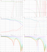
This XO gives my ear the "one stage" sound. I attribute it to the even sound power. For me, this was the first speaker of mine to really pull off this sound. But I also have a fast GD and very minimal diffraction so there is that at play too.
IMO distortion is completely overrated. How many -50db distortion speakers are there with +10db diffraction baffles? This is what happens with magic bullet thinking.But every technical performance measure has a limit of audibility,
This is something I have been trying to nail down too. How can I get a ceiling bounce that looks like the on-axis? The only way seems to be not to have the woofer play into the tweeter. I think a big perk of having a tweeter/horn away from the woofer is not having them interact in ways you do not want. I had lots of problems with a 0.48WL spacing speaker.I've become interested in wide and smooth horizontal response, but also constrained and smooth vertical response.
It should be the starting point of any idea. Kuddos to Kimmo!In addition we have great tools like VituixCAD
This is also the kind of thinking that can lead things astray. Some types of distortion are very audible in extremely tiny amounts and are not masked by high levels of low order THD or other deficiencies in the response. The only real way to try and find out what matters is through perception studies and even then there can be unforeseen interactions between variables that render the results questionable.IMO distortion is completely overrated. How many -50db distortion speakers are there with +10db diffraction baffles? This is what happens with magic bullet thinking.
I noticed with my line arrays that they rendered most music really well and were not only able to sound good with selected genres like other speakers before. The difference between high and low vertical directivity wasn't immediately obvious it wasn't a tonality shift it wasn't something EQ could change but over time I am now convinced the high vertical directivity is responsible for this.My experience is that hard floors and the typical 8' ceiling really muck up the sound, and I wanted to remove it by constraining it to some degree, but also make it smooth so at least it blends with the horizontal sound well. The 1.2x ctc helps do that. A speaker that really showed this behavior is the Perlisten bookshelf speaker tested by Erin, and which is extremely well received critically.
I think the desire for lower crossover frequencies is directly linked to the thinking that closer is always better, because when you can't make it close enough the answer is to lower the crossover frequency. No one thinks to try the opposite and raise the crossover frequency and see what they get.The ability to raise a crossover, or at least use a formerly common 2.5-3.0khz, is actually easier with a waveguide.
Both of these things were touched on by kimmo in some posts he made here
https://www.audiosciencereview.com/forum/index.php?threads/some-help-with-lobing.22661/post-755427
Cheers. I could have written that better. I meant for it more to be a slam on focusing on just the distortion.This is also the kind of thinking that can lead things astray. Some types of distortion are very audible in extremely tiny amounts and are not masked by high levels of low order THD or other deficiencies in the response. The only real way to try and find out what matters is through perception studies and even then there can be unforeseen interactions between variables that render the results questionable.
I do look at the distortion and how linear it is.
Hi, long time since last post in this thread 🙂
Back to business, here is small test to see what happens to DI around crossover with a waveguide mated to monopole, dipole and cardioidish woofer configuration.
Motivation was to see see shape of DI and whether any hump exists at crossover. Here crossover is LR24 at 1100Hz, observation is on-axis to waveguide, woofer is 34cm below, roughly 1.1wl c-c. Woofer responses are generated with VCAD diffraction tool. Waveguide is 26cm in diameter, whipped up in ATH and simulated in ABEC3. Well, ideal responses all along of a system that I think would work nicely together. Waveguide DI can be changed at will with ATH and might change results some depending on what it was.
Setup consists of crossover filters and a delay block.
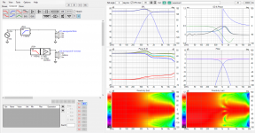
Waveguide alone
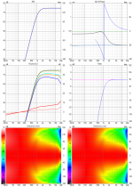
Then ideal ~6", ~8" and ~10" monopole and dipole, both on minimal baffle (no bigger than driver). As bonus emulated 8" hyper cardioidish and 8" cardioid like pattern in minimal baffle. Also ideal monopole tested with no baffle at all, for fun.
Here some of them alone to give an idea of DI:s of the various woofers. 10" and 6" variations would have the DI shape start bit lower or higher.
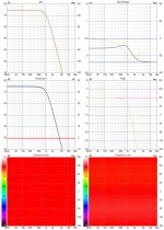
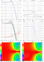
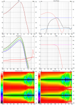
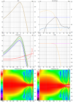
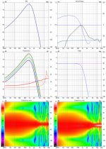
Ok here is the set:
8" woofer
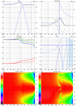
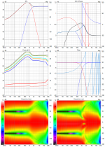
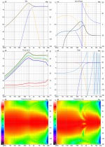
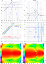
6" woofer
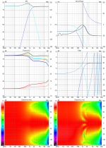
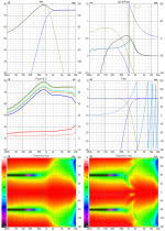
10" woofer
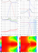

Ideal monopole
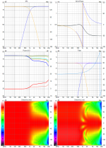
Example without delay block to illustrate hump:
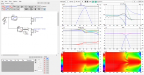
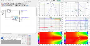
Example if c-c was as close as possible, 23cm instead of 34cm. Delay adjusted and DI is pretty much fine, but not as smooth. Shape of DI is basically the same though. Compare to the two images above.
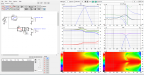
Observations:
With the delay block I was able to smoothen out DI on all of the examples. Didn't prepare for it but it felt like a magic tool here. All configurations would all have some bump at crossover without adjusting delay and each would need varying amount of delay to smoothen it out. Observation from this is that DSP can help flatten DI around crossover with adjustable delay. Cardioidish variety seemed to have too high of a DI for the waveguide and I couldn't get as smooth transition as with the others.
Another observation is that all of the configs, quite different sized woofers worked just fine with the same waveguide.
Main observation, shape of DI on all of the examples for reference.
Do not pay attention to other responses on six pack image than DI as they can be just EQ:d. Polar maps are normalized to illustrate if system was EQ:d flat. No comments on which would sound best, purpose of this experiment was to inspect shape of DI.
Feel free to make observations on it 🙂
Back to business, here is small test to see what happens to DI around crossover with a waveguide mated to monopole, dipole and cardioidish woofer configuration.
Motivation was to see see shape of DI and whether any hump exists at crossover. Here crossover is LR24 at 1100Hz, observation is on-axis to waveguide, woofer is 34cm below, roughly 1.1wl c-c. Woofer responses are generated with VCAD diffraction tool. Waveguide is 26cm in diameter, whipped up in ATH and simulated in ABEC3. Well, ideal responses all along of a system that I think would work nicely together. Waveguide DI can be changed at will with ATH and might change results some depending on what it was.
Setup consists of crossover filters and a delay block.

Waveguide alone

Then ideal ~6", ~8" and ~10" monopole and dipole, both on minimal baffle (no bigger than driver). As bonus emulated 8" hyper cardioidish and 8" cardioid like pattern in minimal baffle. Also ideal monopole tested with no baffle at all, for fun.
Here some of them alone to give an idea of DI:s of the various woofers. 10" and 6" variations would have the DI shape start bit lower or higher.


Ok here is the set:
8" woofer


6" woofer


10" woofer


Ideal monopole

Example without delay block to illustrate hump:


Example if c-c was as close as possible, 23cm instead of 34cm. Delay adjusted and DI is pretty much fine, but not as smooth. Shape of DI is basically the same though. Compare to the two images above.

Observations:
With the delay block I was able to smoothen out DI on all of the examples. Didn't prepare for it but it felt like a magic tool here. All configurations would all have some bump at crossover without adjusting delay and each would need varying amount of delay to smoothen it out. Observation from this is that DSP can help flatten DI around crossover with adjustable delay. Cardioidish variety seemed to have too high of a DI for the waveguide and I couldn't get as smooth transition as with the others.
Another observation is that all of the configs, quite different sized woofers worked just fine with the same waveguide.
Main observation, shape of DI on all of the examples for reference.
Do not pay attention to other responses on six pack image than DI as they can be just EQ:d. Polar maps are normalized to illustrate if system was EQ:d flat. No comments on which would sound best, purpose of this experiment was to inspect shape of DI.
Feel free to make observations on it 🙂
Last edited:
Cool. 😎
A couple of thoughts and questions... Where did you get the waveguide data, is it measured from a a tweeter in a waveguide, or is it simulated?
Do you have in mind a particular tweeter that can be crossed as low as 1.1k ? Even with a lot of waveguide gain, that seems a bit sporty for most tweeters. A Bliesma T34B might do it. There are a couple of ScanSpeaks and Morels that might do it. Thoughts?
J.
I now see where you stated you used ATH for simulation... sorry.Where did you get the waveguide data, is it measured from a a tweeter in a waveguide, or is it simulated?
If you put the T34A in much of a waveguide looking to get gain low down it will come at the expense of some cancellation high up. The driver is strong enough to get close on it’s own or in a small waveguide. Even at 8mm deep a waveguide starts to get interference from the dome.T34A in a waveguide…
The T34B is the part to get if you want a big waveguide or anything other than a super wide pattern.
- Home
- Loudspeakers
- Multi-Way
- VituixCad Simulations with Ideal Drivers