Member
Joined 2003
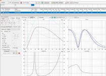
You will probably find the frequency response is slightly different too. I would expect the two phase response to overlap at some point if timing is indeed the same between the two. Simple comparison on my end shows perfect overlap from <1kHz. Only phase difference here is due to change in response at high freq.

First thing I would make sure of is the resampling options in REW are disabled per VCAD instructions:

First thing I would make sure of is the resampling options in REW are disabled per VCAD instructions:
That's very strange! Timing is the same, and IR Calculation options are exactly like yours (and per VCAD)You will probably find the frequency response is slightly different too. I would expect the two phase response to overlap at some point if timing is indeed the same between the two. Simple comparison on my end shows perfect overlap from <1kHz. Only phase difference here is due to change in response at high freq.
But no big deal I guess, I'm only using the “Use loopback as cal and timing reference” from now on anyways 🙂
Member
Joined 2003

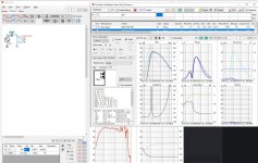
Just for the sake of experimenting, I have made new measurements for tweeter and woofers. But this time, instead of measuring at each drivers axis, I have measured the two woofers together as a pair on tweeter axis. @DcibeL I know very well that this is not good practice and not something you will recommend 🙂 I just want to see for myself the effect of measuring this way.
But is it even possible to use measurements like these in VCAD? I mean the two woofers in the MTM config will have to be imported as one driver with presumably the same x & y coordinates as the tweeter? I know this seems like a mess, but please bear with me 🙂
But is it even possible to use measurements like these in VCAD? I mean the two woofers in the MTM config will have to be imported as one driver with presumably the same x & y coordinates as the tweeter? I know this seems like a mess, but please bear with me 🙂
Member
Joined 2003
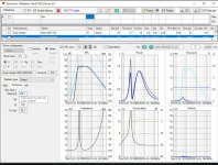
You will be slightly off-axis measurement and may have some effect on power & di chart since driver will be treated as singular audio source, so vertical directivity chart will be incorrect. MTM can present some additional small challenges, but really since both drivers are the same you really only need to measure one.
For far field measurement, simply disconnect one driver. With only one driver connected, cabinet interaction will be incorrect, but should not be of significance for far field measurement from >200Hz. For near field measurement, measure with both drivers connected so correct cabinet effect is included for low frequency measurement.
In-box impedance can be measured with both drivers in parallel, however for single driver in crossover, scale measured impedance accordingly. Scale by 2 for parallel, scale by 0.5 for series connected drivers.
With this in mind, responses can be merged, 2 instances of same driver placed in crossover with correct x,y offset.
Thanks DciBeL, problem is I can't just disconnect one driver. The crossover and design was finalized months ago, so wires are soldered to driver terminals and speaker binding posts. This is why I wanted to make this simple experiment measuring both together. Crossover is outboard however, so this can be easily disconnected for raw driver responses.For far field measurement, simply disconnect one driver. With only one driver connected, cabinet interaction will be incorrect, but should not be of significance for far field measurement from >200Hz. For near field measurement, measure with both drivers connected so correct cabinet effect is included for low frequency measurement.
Nearfield and impedance measurements are also done, I'm just not sure how to combine the nearfield/farfield measurements in the Merger tool with both woofers measured as a pair, and then how to use these woofer measurements in VCAD.
Member
Joined 2003
Can't? If you're going to be designing crossovers, you're going to need a soldering iron.
Merge the responses like you would a single driver, treat the pair like a single driver.
Merge the responses like you would a single driver, treat the pair like a single driver.
This produces slightly wrong timing and frequency response. What is the purpose of all this? Just to publish something which confuses other users and forces us to comment that method is wrong....instead of measuring at each drivers axis, I have measured the two woofers together as a pair on tweeter axis
I stated very clearly my purpose for doing this, did you read my post at all?This produces slightly wrong timing and frequency response. What is the purpose of all this? Just to publish something which confuses other users and forces us to comment that method is wrong.
I have no intentions of publishing any of these measurements here, so don't worry.
Like I just wrote to kimmosto, it is very clear from my post that my only intention for measuring like this is to understand why it is the wrong procedure. And see for myself the result of this. Learning by doing, right..? And one can certainly learn from doing things the wrong way.Can't? If you're going to be designing crossovers, you're going to need a soldering iron.
Merge the responses like you would a single driver, treat the pair like a single driver.
But no worries, I will try to figure this out without your help.
Member
Joined 2003
I understand DciBeL. I still think experimenting and seeing the effects of doing things the wrong way can be a good path to learning.You were seeking advice on how to do something incorrectly, don't be surprised that the advice is to take a different approach.
But I also understand that it may be confusing for others looking for advice in this thread, so I will not be going forward with this approach.
And for the record, I already did the correct measurement procedure a while ago much thanks to you (and others) 🙂
Hope this thread is still active.
I'd like to know if VC can simulate the GHP series-cap bass boost trick in a "too small" closed box,
From what I understand, you calculate VB for a QTC of 1.0, use that volume and add a 600uf or so capacitor in series with the woofer.
I'm trying to do this in VC but the F3 calculated in the info screen never goes below the F3 calculated normally for a QTC of 0.7 or even 1.0
e.g. using 26W/8534 from enclosure tab,
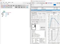
1. I choose closed box QTC 0.7, auto-align > VB = 65.2L & info tab F3 = 44hz
2. Then I change QTC = 1.0, auto-align > VB = 26L & info tab f3 = 55.8hz - it now shows a bump in the bass response
3. Using VB = 26L, I check feed speaker and check use crossover for driver 1 and insert a series cap of 580uf in the crossover.
But changing the value of the cap up and down doesn't lower the f3 , and min F3 I get is 56.6hz with a 1200uf cap.
I tried using the FRD and ZMA files and also leaving them out, but the F3 results don't change.
Am I doing something wrong?
I'd like to know if VC can simulate the GHP series-cap bass boost trick in a "too small" closed box,
From what I understand, you calculate VB for a QTC of 1.0, use that volume and add a 600uf or so capacitor in series with the woofer.
I'm trying to do this in VC but the F3 calculated in the info screen never goes below the F3 calculated normally for a QTC of 0.7 or even 1.0
e.g. using 26W/8534 from enclosure tab,
1. I choose closed box QTC 0.7, auto-align > VB = 65.2L & info tab F3 = 44hz
2. Then I change QTC = 1.0, auto-align > VB = 26L & info tab f3 = 55.8hz - it now shows a bump in the bass response
3. Using VB = 26L, I check feed speaker and check use crossover for driver 1 and insert a series cap of 580uf in the crossover.
But changing the value of the cap up and down doesn't lower the f3 , and min F3 I get is 56.6hz with a 1200uf cap.
I tried using the FRD and ZMA files and also leaving them out, but the F3 results don't change.
Am I doing something wrong?
Attachments

I'm going to ask a question that has probably been answered many times, but search is not helping.
I have created a new project with one driver. I have the enclosure set up with the driver I want. But can't seem to get it to the driver tab.
SPL export with feed speaker check don't help.
Even ChatGPT can't educate me.
I have created a new project with one driver. I have the enclosure set up with the driver I want. But can't seem to get it to the driver tab.
SPL export with feed speaker check don't help.
Even ChatGPT can't educate me.
- Open VituixCAD:
- Launch the VituixCAD program on your computer.
- Create or Open a Project:
- Start a new project or open an existing project where you want to work on the speaker design.
- Enter Enclosure Tool:
- Navigate to the enclosure tool within the software. This is the section where you design the enclosure for your speaker system.
- Configure the Enclosure:
- Input the necessary parameters such as box type, dimensions, and tuning frequency to design the enclosure for your speaker.
- Add Drivers to the Enclosure:
- Within the enclosure tool, you should have the option to add drivers to the design. This typically involves specifying the characteristics of the drivers you plan to use, such as their model, parameters, and placement within the enclosure.
- Transfer Driver Information:
- After adding the drivers to the enclosure tool, there should be an option to transfer or export this driver information to the drivers tab. Look for a button or menu option that allows you to transfer the configured drivers to the main driver database or the drivers tab.
- Verify Driver Information:
- Once the transfer is complete, navigate to the drivers tab or the main driver database within VituixCAD. Verify that the information for the drivers you added in the enclosure tool is now present in the drivers tab.
- Fine-Tune Driver Settings (if needed):
- In the drivers tab, you may have additional options to fine-tune individual driver settings. Ensure that all driver parameters are accurately represented.
- Save Your Project:
- After transferring the driver information and making any necessary adjustments, remember to save your project to preserve the changes.
The auxiliary tools, like enclosure tool or diffraction tool can export simulated "measurement data". Most of the tools are just to manipulate data.
The main program works so that you would have a "driver" per dataset, measurements of single driver in a fully built enclosure.
When you open the program there is one driver, you can rename it, add more drivers, as many as you have (measurements for) in your speaker. Still on the drivers tab, suitable driver selected, you would load in messurement data for that, be it simulated or real measurements. SPL, impedance, what have you.
To get the graphs show something, you must add wire from voltage source to the driver(s).
Please resort to VituixCAD measurement manual. Even if you don't measure real speaker but use simulated data instead, it is helpful to think the sims as real measurements. Read the manual as many times as needed to understand why is everything done like instructed. Have fun! 🙂
ps. simulated data is just indicator, and cannot result best result, which can be obtained only with real data, a complete fully built speaker measured properly.
I just skimmed through this thread, I did not read it in depth.
It occurred to me that many new users of VituixCad seem to struggle with becoming familiar with the software because they do not have any real measured data to work with. I remember facing this same hurdle myself.
I could provide a set of polar response data and impedance data for 3 drivers (large woofer, midwoofer, tweeter). New VituixCad users could use this data to get comfortable with the software.
If this would be helpful, I can do this. But I don't want to duplicate someone else's work. Is there a ready source for this kind of data already in existence? Would this be helpful?
j.
- Home
- Design & Build
- Software Tools
- VituixCAD For Newbies