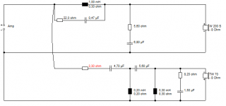
I quote it since we are turning the page.Just my 2 pence
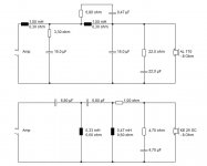
The values of capacitors aren't right in my diagram, but note the single coil I added to the Visaton circuit.
The vib130tl circuit is here:
VIB 130 TL
Its simpler and kills the breakup of the AL130 well enough)
Its basically the Vib130TL circuit, with an added coil shunting the LP circuit to notch the breakup. Seems to do OK. Would be easy to try if you have spare components 🙂
Designing a 4th order ELECTRICAL crossover was too problematic and almost unnecessary in my opinion

From experience, I don't mind complex crossovers at all. 4th order tweeter filters sound excellent if you accept the 24dB/octave LR4 sound. vulejov has done a meticulous job here. Sure they are harder to fit in a small space and cost more money usually, but think of a fourth order as a DISTRIBUTED filter and it makes sense. Instead of a single 2.2mh coil and capacitor, the bass uses two smaller coils and two smaller capacitors and gets steeper. Why should that sound worse? In fact it sounds better IMO.
The only real reason to use simple filters is COST IMO. Not quality. And a metal driver is an awkward thing at the best of times. It needs steep to tame the ringing. Try 12dB/octave LR2 with drivers with less issues. 😎
I prefer to think of 4th order as two filters with independently variable Fc.
No matter. The OP filter is more two cascaded LP + notch, plus a further notch.
Almost two cascaded elliptical plus a notch.
Phase reversal is audible, and this filter shows inversion** despite looking like 4th order to some.
The point, to me, of going to these kind of lengths is to gain attenuation, and not have the phase inversion of 2nd order filters.
** Caveat being:
The OP measured and Boxsim phase graphs differ in that inversion is present at the crossover point in measured but not simmed.
Perhaps a wiring error?
Last edited:
just out of interest....
I tried this design in Boxsim...
I agree with Sreten (still)
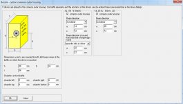
I simulated using my box dimensions, and then to double check I estimated the OPs dimensions from photograph posted.
I guessed the dimensions using volume stated and assuming golden ratio. I also assumed the Driver positions (not having the OPs) and copied the filter. Port at 8cm from bottom, AL130 at 17cm, and G20SC at 33cm with 1 cm offset.
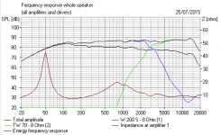
The 'Tank' circuits are quite resonant, causing a rise of ~10dB from 500-2kHz, followed by a similar amplitude drop in output at the crossover, where it hands over to the tweeter which has a rising response of some 10 dB from XO to 20kHz.
The Tanks are countering the BSC (if desired) and so are counter productive.
Also the value of C in the second tank circuit is too small, the notch is centred at 11-12k, rather than the desired 7k.
Increasing from 0.47uF to 1uF centres the notch correctly, but leaves other issues unsolved.
Whilst flat in room response is shown in the other plot, IF the Boxsim design actually matches that of the completed speaker, then at the very least there is a notch which is doing nothing here, AT ALL.
I can only assume the flat in room measurement is the result of crossover tweaking and that BSC was not required at all in the room.
However, there are multiple components here that are not doing anything useful at all. The design could and probably should be simplified a lot and the result IN ROOM could be identical to that which was already posted.
I tried this design in Boxsim...
I agree with Sreten (still)
I simulated using my box dimensions, and then to double check I estimated the OPs dimensions from photograph posted.
I guessed the dimensions using volume stated and assuming golden ratio. I also assumed the Driver positions (not having the OPs) and copied the filter. Port at 8cm from bottom, AL130 at 17cm, and G20SC at 33cm with 1 cm offset.
The 'Tank' circuits are quite resonant, causing a rise of ~10dB from 500-2kHz, followed by a similar amplitude drop in output at the crossover, where it hands over to the tweeter which has a rising response of some 10 dB from XO to 20kHz.
The Tanks are countering the BSC (if desired) and so are counter productive.
Also the value of C in the second tank circuit is too small, the notch is centred at 11-12k, rather than the desired 7k.
Increasing from 0.47uF to 1uF centres the notch correctly, but leaves other issues unsolved.
Whilst flat in room response is shown in the other plot, IF the Boxsim design actually matches that of the completed speaker, then at the very least there is a notch which is doing nothing here, AT ALL.
I can only assume the flat in room measurement is the result of crossover tweaking and that BSC was not required at all in the room.
However, there are multiple components here that are not doing anything useful at all. The design could and probably should be simplified a lot and the result IN ROOM could be identical to that which was already posted.
Last edited:
Mondogenerator has plan to sell PCB for active filter..
It would be fair to open thread about it, and not poison mine..
VIB xover is not too serious.. AL130 7-8kHz ringing must be well attenuated, 30-40dB at least..
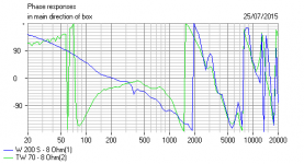
FR with my xover is first, second one is VIB130TL..
It would be fair to open thread about it, and not poison mine..
VIB xover is not too serious.. AL130 7-8kHz ringing must be well attenuated, 30-40dB at least..
FR with my xover is first, second one is VIB130TL..
Attachments

4th order tweeter filters sound excellent if you accept the 24dB/octave LR4 sound.
Hi,
Except LR4 acoustic is hardly ever implemented with 4th order electrical.
rgds, sreten.
vulejov, that looks like a very accurate 3kHz LR4 indeed. Enjoying your exploits. 😎
I'm quite surprised you wire negative polarity for LR4 here, and mondo positive for near LR2 with such a shallow bass. I must run the sim. Metal drivers seem to have very flat power response due to a very pistonic nature, I suppose.
The LR4 sound IMO is that at crossover, there is a notch in the frequency response above and below axis. On the other hand, the drivers sound very integrated at the sweet spot and distortion is low. 18dB/octave BW3 is a different animal with a more natural response off-axis.
An 8" paper bass is altogether easier on filters, needing only second order electrical with a 7kHz tank notch. But the 4th order electrical tweeter below sounds very good. It's a design choice. Take it or leave it.
Attachments
I was thinking about similar combination..
Attachments
Last edited:
I'm quite surprised you wire negative polarity for LR4 here, and mondo positive for near LR2 with such a shallow bass. I must run the sim. Metal drivers seem to have very flat power response due to a very pistonic nature, I suppose.
.
Mine is inverted, as is usual for 2nd order.
Please do sim the circuit from post one,perhaps you can help me understand why the graph I get bears no resemblance at all to Vulejov graphs.
Vulejov...have you used your own .frd and .zma files?
First post have measured FR and final xover..
Boxsim files are slightly different.. tweeter needed greater resistor.. measurements with RC filter was better, but we don't hear any difference, so final xover version is without..
Boxsim files are slightly different.. tweeter needed greater resistor.. measurements with RC filter was better, but we don't hear any difference, so final xover version is without..
Attachments


@ Vulejov
Ok I see.
Thanks for the information.
It was not my intention to have arguments with you, or to poison a thread.
I am just trying to help.
I have looked at your circuit from post #1 and when I use the component values the result is very poor.
Your changes to circuit explain the poor result I found, and the difference in our results.
For your interest I include a design worked on this morning since my last post.
It is not perfect, but may be interesting to you, and is in the context of this thread.
I will also attach Boxsim project file for you. (I assumed dimensions based on your photographs and stated volume)

Filters:


Boxsim outputs:


Again, I repeat that this is maybe 30 minutes work, and needs adjustment.
Once again, its great to see someone else using these two speakers. I love them!
EDIT: I guessed your driver positions, so please excuse the differences. But I'm pleased that I guessed quite well.
One small criticism of your Low Pass filter: Its may be 4th order in electrical layout, but the attenuation is not. In fact it is very similar to my implementation which resembles 2nd order with a following notch. Its good, but does not achieve the attenuation that is possible.
Your High Pass filter, is much much better above the crossover point (but I use 500 points in Boxsim and I assume the ripple is caused by my use of incorrect driver positions relative to each other)
Ok I see.
Thanks for the information.
It was not my intention to have arguments with you, or to poison a thread.
I am just trying to help.
I have looked at your circuit from post #1 and when I use the component values the result is very poor.
Your changes to circuit explain the poor result I found, and the difference in our results.
For your interest I include a design worked on this morning since my last post.
It is not perfect, but may be interesting to you, and is in the context of this thread.
I will also attach Boxsim project file for you. (I assumed dimensions based on your photographs and stated volume)
Filters:
Boxsim outputs:
Again, I repeat that this is maybe 30 minutes work, and needs adjustment.
Once again, its great to see someone else using these two speakers. I love them!
EDIT: I guessed your driver positions, so please excuse the differences. But I'm pleased that I guessed quite well.
One small criticism of your Low Pass filter: Its may be 4th order in electrical layout, but the attenuation is not. In fact it is very similar to my implementation which resembles 2nd order with a following notch. Its good, but does not achieve the attenuation that is possible.
Your High Pass filter, is much much better above the crossover point (but I use 500 points in Boxsim and I assume the ripple is caused by my use of incorrect driver positions relative to each other)
Attachments
Last edited:
Thanx for filter.. with my box dimensions looks like this.. you have only 16cm wide box, AL130 is not in middle..
Tweeter filter is better, but I don't like AL130 7-9kHz resonance..
Tweeter filter is better, but I don't like AL130 7-9kHz resonance..
Attachments
Last edited:
With respect, using your box size does not look like that.
Box.dimensions will.not affect the 7khz resonance.
What will make the resonance appear again is increasing resistance in the woofer lowpass circuit, particularly the shunting components.
In all shunt components you require as low DCR as possible in order to ensure the notch is of a high Q and effective at suppressing this resonance.
You have increased resistance somewhere.
Box.dimensions will.not affect the 7khz resonance..
I agree..
But frequency response of both drivers dramatically changes with differen front panel layout.. try small corrections of your filter with real dimension of my box.. it is much easier to change xover than box..
Attachments
Last edited:
Vulejov, I am in agreement about driver positions.
however, this is what my filter (post #30) looks like in Boxsim, with the correct dimensions you supplied in post #29

As you can see the AL130 7 khz resonance is still better than -40dB
however, this is what my filter (post #30) looks like in Boxsim, with the correct dimensions you supplied in post #29
As you can see the AL130 7 khz resonance is still better than -40dB
Last edited:
Try to set view options from 20 or 30dB..
You have +1-2dB on 1kHz, but this is not very important.. that is why my filter have 1mH_15R_32u LRC..
You have +1-2dB on 1kHz, but this is not very important.. that is why my filter have 1mH_15R_32u LRC..
Last edited:
Try to set view options from 20 or 30dB..
Sorry but I do not understand your meaning.
EDIT: I found the option you describe. 20dB is not audible, 30dB is around the threshold of audibility of the human ear. I have changed the option anyway.
You have +1-2dB on 1kHz, but this is not very important.. that is why my filter have 1mH_15R_32u LRC..
That is correct. This is due to the driver and baffle size. I have a smaller peak in my own speakers using these drivers, but this uses a simpler crossover filter. In both my speakers and your speakers the baffle step compensation of the inductor/s is set at around 700 Hz. This is about right for the baffle width we are both using.
What I have found when trying to use a more complex filter such as yours, is that when I adjust the second low pass stage to increase the stop band attenuation, and flatten the in band response, then what happens is the woofer response tends to 'bunch up' at 1-2khz.
You choose to use a contour filter to scoop this area and flatten 1-2kHz again.
Its is a matter of opinion, but it can be argued that it is not necessary as we both have nearly full BSC applied here, and that real in-room measurements may not show this rise to be detrimental.
Adding corner mitre of 5cm, and adjusting the total width to include this extra width improves the response considerably. I believe that neither you or I have used any corner mitre.
(I have thought of adding 5cm timber to the cabinet sides to provide the mitre, and gain some improvement.
Last edited:
Hi again.
For what it is worth, when I used 2nd order filters this problem did not occur.
AT 7k I still achieve -35dB attenuation.
when I look at this passive design again today, and try to add components to improve the filter it is easier to stop at third order for the woofer. Adding more stages to make 4th order adds problems that didn't exist in the simple filter.
Its all a compromise, and the higher in filter order I go(>2nd order), the less 'room' exists for improvement without increased compromise in other areas.
Simply put: I end up going around in circles like a dog chasing his tail.
Simply put: I end up going around in circles like a dog chasing his tail.
So I declare my project with those two drivers good enough (for me)..
..and starting simulation for AL170_KE25SC combo..
Hahaha you read my mind. Ive already done it some time ago.
The worst thing for me is that the KE25c is so very much easier to work with!!!
Phase just line up perfectly! You will almost use an identical filter, but with better results, and less effort.
Its much the same with Fountek neo3.5H, less effort, easier to work with.
The G20sc is just a pain to work with.
I wish I had just saved harder and bought the ceramic dome instead 🙁
Its on order when I get paid 🙂
..and starting simulation for AL170_KE25SC combo..
Attachments

- Status
- Not open for further replies.
- Home
- Loudspeakers
- Multi-Way
- Visaton AL130_G20SC