[FONT=Arial,Helvetica]
Virtual Ground Circuits from Voltage Regulators[/FONT]
[FONT=Arial,Helvetica] Virtual Ground Circuits from Voltage Regulators[/FONT]
[/FONT]
[FONT=Arial,Helvetica][SIZE=-1]These circuits enable a twp conductor DC power supply, DC wall adapter, or a battery to function as a split supply with a three conductor output (i.e., positive, negative AND ground). This sort of circuit is called a "Virtual Ground" and/or a "Rail Splitter".
The inexpensive LM317/LM337 circuits below are capable of delivering up to +/-18V at more than 1.5 amps, 75 times the current of a TLE2426 rail splitter chip. [/SIZE][/FONT][FONT=Arial,Helvetica][SIZE=-1][FONT=Arial,Helvetica][SIZE=-1]The DC Supply Input can be from 7.5VDC to 40VDC. [/SIZE][/FONT]The TO-220 voltage regulators are each rated for 20W. However, they can handle a watt or more without heatsinks -
example: Output = +/- 9VDC @ 50mA.
Both the LM317/LM337 Basic and VG1 Circuits below draw quiescent current of only 4 or 5 milliamps - great for battery use![/SIZE][/FONT]
[FONT=Arial,Helvetica][SIZE=-1]
Basic Circuit with Adjustable Voltage Regulators[/SIZE][/FONT]
[FONT=Arial,Helvetica][SIZE=-1][SIZE=-1] NOTES:
1) The values for R1 and R2 shown in the chart above yield about 2mA of current through the LM336BZ-2.5V. The formula used to determine the values is: R1 or R2 = (Vrr - 2.5) / .002 / 2 For example with a 12V power supply:
(12 - 2.5) /.002 / 2 = 2375. So use a 2.37K resistor for R1 & R2. Also: I = (DC supply - 2.5) / (R1+R2).
2) The adjust pin on the LM336 voltage reference is not used, so leave it unconnected;
only connect the "+" and "-" pins.
3) When using an AC powered DC supply, "proper power supply design" recommends C1, C2, C3, C4, C5, D1,
and D2 be installed. But when using a 9V battery for a low current application you can skip installing C1, C2, C3, C4, C5, D1, D2, D3 and D4 altogether - and simply use the Basic Circuit as shown at the top of the page!
4) A "no load test" of the VG1 Circuit with an Eveready Gold 9V alkaline battery (it actually measured 9.3V) and 1.62K R1/R2 resistors yielded the following results: The ground remained perfectly centered (+/- 4.65V), while the total current being drawn was only about 4.5mA. This shows that with 2mA through the voltage divider section, the rest of the circuit was consuming only an additional 2.5mA. And that says if we add a 20mA load to the output, and if the 9V battery could supply 350mAH to 550mAH, the battery would last about 12 to 20 hours or more of continuous use.
5) You may be able to reduce the size of the 1 ohm output resistors to 0.75 ohm or less by minimizing the current through the LM336BZ-2.5 (by using larger value R1/R2 resistors). A small ground point voltage offset, if it happens, is usually acceptable. An LM336BZ-2.5V can operate with 0.5mA to 10mA of forward current.
6) The LM317/LM337s require about 1.5 to 6mA of load current to maintain regulation - and they will continue to regulate with an Input voltage as low as 3.7 volts.
7) Increasing the size of C1, C4 and C5 can be sonically advantageous. They can be 220uF to 12,000uF, (or as much as you can afford or have room for.) Generally, electrolytic capacitor rated voltages should be at least 30 percent higher than whatever their power supply voltage is.[/SIZE][/SIZE][/FONT]___ [FONT=Arial,Helvetica][SIZE=-1][SIZE=-1]
[/SIZE][/SIZE][/FONT]
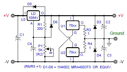
[/SIZE][/SIZE][/FONT][/SIZE][/SIZE][/SIZE][/SIZE][/FONT] If you are using the virtual ground with an audio circuit and your DC power supply has an AC source, adding another voltage regulator in front of the rail splitter section can further improve sound quality. An LD1085V, 3A LDO (Low Dropout Voltage) voltage regulator sounds better for this purpose than others I've compared by listening tests. When using this additional voltage regulator (U4), be sure that your DC Supply (input voltage) is always 1.5V (or more) higher than your desired LM317/LM337 rail-to-rail voltage - because the LD1085V needs at least 1.3V across it to stay in regulation. note: The maximum DC Input Voltage for a LD1085V is 30VDC.[FONT=Arial,Helvetica][SIZE=-1][SIZE=-1] (This three regulator circuit draws twice the current (or more) compared to the VG1 Circuit, so it may not be as well suited for battery use.)
[/SIZE][/SIZE][/FONT]
[FONT=Arial,Helvetica][SIZE=-1]
Enhanced Virtual Ground for Low Noise Audio Applications
[/SIZE][/FONT][FONT=Arial,Helvetica][SIZE=-1][SIZE=-1]
[/SIZE][/SIZE][/FONT]
[FONT=Arial,Helvetica][SIZE=-1] [SIZE=-1] Development Credits:
[/SIZE][/SIZE][/FONT][FONT=Arial,Helvetica][SIZE=-1][SIZE=-1]Arn Roatcap: (Founder of Goldpoint Level Controls [/SIZE][/SIZE][/FONT][FONT=Arial,Helvetica][SIZE=-1][SIZE=-1][FONT=Arial,Helvetica][SIZE=-1][SIZE=-1]www.goldpt.com[/SIZE][/SIZE][/FONT]) - Prior to the LM317/LM337 circuits, built virtual grounds using fixed value voltage regulators (see circuits below). Integrated new ideas, constructed all of the prototypes and performed extensive listening tests.
John Broskie: (GlassWare www.glass-ware.com and Tube CAD www.tubecad.com) - Suggested many virtual ground circuit ideas from 2006 to 2013. Directed the use of 1 ohm output resistors on the rail splitter voltage regulators.[/SIZE][/SIZE][/FONT][FONT=Arial,Helvetica][SIZE=-1][SIZE=-1]
Kim Laroux: (www.head-fi.org forums) - Had the ingenious idea to offset the LM317/LM337 internal voltage references by using a single 2.5V zener diode.
KT88: (www.head-fi.org forums) - Contributed the key idea to use a LM336 voltage reference, instead of a zener diode, to compensate the LM317/LM337 internal voltage references.[/SIZE][/SIZE][/FONT]
The inexpensive LM317/LM337 circuits below are capable of delivering up to +/-18V at more than 1.5 amps, 75 times the current of a TLE2426 rail splitter chip. [/SIZE][/FONT][FONT=Arial,Helvetica][SIZE=-1][FONT=Arial,Helvetica][SIZE=-1]The DC Supply Input can be from 7.5VDC to 40VDC. [/SIZE][/FONT]The TO-220 voltage regulators are each rated for 20W. However, they can handle a watt or more without heatsinks -
example: Output = +/- 9VDC @ 50mA.
Both the LM317/LM337 Basic and VG1 Circuits below draw quiescent current of only 4 or 5 milliamps - great for battery use![/SIZE][/FONT]
[FONT=Arial,Helvetica][SIZE=-1]
Basic Circuit with Adjustable Voltage Regulators[/SIZE][/FONT]
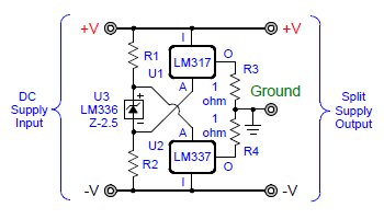
[FONT=Arial,Helvetica][SIZE=-1]How it works: The LM317 (positive) and LM337 (negative) adjustable voltage regulators operate in parallel with their outputs tied together through small resistors to create a virtual ground. The LM336BZ-2.5V voltage reference compensates for the LM317's (+1.25V) internal reference and the LM337's (-1.25V) internal reference. So when the LM317/LM337 adjust pins are connected inside the R1/R2 voltage divider as shown, each voltage regulator output voltage becomes 1/2 of whatever the rail-to-rail voltage happens to be. Thus, together, the voltage regulators "split the rails", creating a "rock solid" virtual ground.
[/SIZE][/FONT][FONT=Arial,Helvetica][SIZE=-1]Although a simple and inexpensive virtual ground solution, some audio designs will sound better when using it. For example, when powering a headphone amplifier with this circuit the bass notes may sound considerably clearer and more life like. The reason for this unusually good performance may be that the voltage regulators create an "unbudgable ground" - holding the ground point in place very firmly compared to other circuits, virtual or not.[/SIZE][/FONT]
[FONT=Arial,Helvetica][SIZE=-1][SIZE=-1]VG1 Parts List:
R1, R2 - (see chart above) - ** dependent on DC Supply voltage
R3, R4 - 0.75 ohm to 1 ohm - 1/2W or 1W
C1 - 470uF/50V** - Panasonic P/N EEU-FM1H471
C2, C3 - 22uF/50V - Panasonic P/N EEU-FM1H220
C4, C5 - 1000uF/25V** - Panasonic P/N EEU-FM1E102
D1, D2, D3, D4 - 1N4002 - (or similar)
U1 - LM317TG - TO-220 package (On Semiconductor)
U2 - LM337TG - TO-220 package (On Semiconductor)
U3 - LM336Z25 - 2.5V voltage reference (Fairchild)[/SIZE][/SIZE][/FONT]
[/SIZE][/FONT][FONT=Arial,Helvetica][SIZE=-1]Although a simple and inexpensive virtual ground solution, some audio designs will sound better when using it. For example, when powering a headphone amplifier with this circuit the bass notes may sound considerably clearer and more life like. The reason for this unusually good performance may be that the voltage regulators create an "unbudgable ground" - holding the ground point in place very firmly compared to other circuits, virtual or not.[/SIZE][/FONT]
[FONT=Arial,Helvetica][SIZE=-1]VG1 Virtual Ground Circuit
[/SIZE][/FONT]
[/SIZE][/FONT]
[FONT=Arial,Helvetica][SIZE=-1]All parts for these various circuits are easy to find - and can be ordered from Mouser.com or Digikey.com. [/SIZE][/FONT]
[FONT=Arial,Helvetica][SIZE=-1] Resistor and capacitor values are not critical - you can substitute near or alternate values.[/SIZE][/FONT]
[FONT=Arial,Helvetica][SIZE=-1] Resistor and capacitor values are not critical - you can substitute near or alternate values.[/SIZE][/FONT]
[FONT=Arial,Helvetica][SIZE=-1][SIZE=-1]VG1 Parts List:
R1, R2 - (see chart above) - ** dependent on DC Supply voltage
R3, R4 - 0.75 ohm to 1 ohm - 1/2W or 1W
C1 - 470uF/50V** - Panasonic P/N EEU-FM1H471
C2, C3 - 22uF/50V - Panasonic P/N EEU-FM1H220
C4, C5 - 1000uF/25V** - Panasonic P/N EEU-FM1E102
D1, D2, D3, D4 - 1N4002 - (or similar)
U1 - LM317TG - TO-220 package (On Semiconductor)
U2 - LM337TG - TO-220 package (On Semiconductor)
U3 - LM336Z25 - 2.5V voltage reference (Fairchild)[/SIZE][/SIZE][/FONT]
1) The values for R1 and R2 shown in the chart above yield about 2mA of current through the LM336BZ-2.5V. The formula used to determine the values is: R1 or R2 = (Vrr - 2.5) / .002 / 2 For example with a 12V power supply:
(12 - 2.5) /.002 / 2 = 2375. So use a 2.37K resistor for R1 & R2. Also: I = (DC supply - 2.5) / (R1+R2).
2) The adjust pin on the LM336 voltage reference is not used, so leave it unconnected;
only connect the "+" and "-" pins.
3) When using an AC powered DC supply, "proper power supply design" recommends C1, C2, C3, C4, C5, D1,
and D2 be installed. But when using a 9V battery for a low current application you can skip installing C1, C2, C3, C4, C5, D1, D2, D3 and D4 altogether - and simply use the Basic Circuit as shown at the top of the page!
4) A "no load test" of the VG1 Circuit with an Eveready Gold 9V alkaline battery (it actually measured 9.3V) and 1.62K R1/R2 resistors yielded the following results: The ground remained perfectly centered (+/- 4.65V), while the total current being drawn was only about 4.5mA. This shows that with 2mA through the voltage divider section, the rest of the circuit was consuming only an additional 2.5mA. And that says if we add a 20mA load to the output, and if the 9V battery could supply 350mAH to 550mAH, the battery would last about 12 to 20 hours or more of continuous use.
5) You may be able to reduce the size of the 1 ohm output resistors to 0.75 ohm or less by minimizing the current through the LM336BZ-2.5 (by using larger value R1/R2 resistors). A small ground point voltage offset, if it happens, is usually acceptable. An LM336BZ-2.5V can operate with 0.5mA to 10mA of forward current.
6) The LM317/LM337s require about 1.5 to 6mA of load current to maintain regulation - and they will continue to regulate with an Input voltage as low as 3.7 volts.
7) Increasing the size of C1, C4 and C5 can be sonically advantageous. They can be 220uF to 12,000uF, (or as much as you can afford or have room for.) Generally, electrolytic capacitor rated voltages should be at least 30 percent higher than whatever their power supply voltage is.[/SIZE][/SIZE][/FONT]___ [FONT=Arial,Helvetica][SIZE=-1][SIZE=-1]
[/SIZE][/SIZE][/FONT]
[FONT=Arial,Helvetica][SIZE=-1][SIZE=-1] [FONT=Arial,Helvetica][SIZE=-1][SIZE=-1][SIZE=-1][FONT=Arial,Helvetica][SIZE=-1][SIZE=-1][SIZE=-1]__________________________ [/SIZE][/SIZE][/FONT][/SIZE][/SIZE][/SIZE][/SIZE][/FONT][/SIZE][/SIZE][/FONT][FONT=Arial,Helvetica][SIZE=-1][SIZE=-1][SIZE=-1][FONT=Arial,Helvetica][SIZE=-1][SIZE=-1][SIZE=-1]__________________________[/SIZE][/SIZE][/FONT][/SIZE][/SIZE][/SIZE][/SIZE][/FONT]
[FONT=Arial,Helvetica][SIZE=-1][SIZE=-1][SIZE=-1][FONT=Arial,Helvetica][SIZE=-1][SIZE=-1][SIZE=-1]
[/SIZE][/SIZE][/FONT][/SIZE][/SIZE][/SIZE][/SIZE][/FONT] If you are using the virtual ground with an audio circuit and your DC power supply has an AC source, adding another voltage regulator in front of the rail splitter section can further improve sound quality. An LD1085V, 3A LDO (Low Dropout Voltage) voltage regulator sounds better for this purpose than others I've compared by listening tests. When using this additional voltage regulator (U4), be sure that your DC Supply (input voltage) is always 1.5V (or more) higher than your desired LM317/LM337 rail-to-rail voltage - because the LD1085V needs at least 1.3V across it to stay in regulation. note: The maximum DC Input Voltage for a LD1085V is 30VDC.[FONT=Arial,Helvetica][SIZE=-1][SIZE=-1] (This three regulator circuit draws twice the current (or more) compared to the VG1 Circuit, so it may not be as well suited for battery use.)
[/SIZE][/SIZE][/FONT]
An externally hosted image should be here but it was not working when we last tested it.
[FONT=Arial,Helvetica][SIZE=-1]
Enhanced Virtual Ground for Low Noise Audio Applications
[/SIZE][/FONT][FONT=Arial,Helvetica][SIZE=-1][SIZE=-1]
[/SIZE][/SIZE][/FONT]
[FONT=Arial,Helvetica][SIZE=-1][SIZE=-1] [FONT=Arial,Helvetica][SIZE=-1][SIZE=-1][SIZE=-1][FONT=Arial,Helvetica][SIZE=-1][SIZE=-1][SIZE=-1]__________________________ [/SIZE][/SIZE][/FONT][/SIZE][/SIZE][/SIZE][/SIZE][/FONT][/SIZE][/SIZE][/FONT][FONT=Arial,Helvetica][SIZE=-1][SIZE=-1][SIZE=-1][FONT=Arial,Helvetica][SIZE=-1][SIZE=-1][SIZE=-1]__________________________[/SIZE][/SIZE][/FONT][/SIZE][/SIZE][/SIZE][/SIZE][/FONT]
[/SIZE][/SIZE][/FONT][FONT=Arial,Helvetica][SIZE=-1][SIZE=-1]Arn Roatcap: (Founder of Goldpoint Level Controls [/SIZE][/SIZE][/FONT][FONT=Arial,Helvetica][SIZE=-1][SIZE=-1][FONT=Arial,Helvetica][SIZE=-1][SIZE=-1]www.goldpt.com[/SIZE][/SIZE][/FONT]) - Prior to the LM317/LM337 circuits, built virtual grounds using fixed value voltage regulators (see circuits below). Integrated new ideas, constructed all of the prototypes and performed extensive listening tests.
John Broskie: (GlassWare www.glass-ware.com and Tube CAD www.tubecad.com) - Suggested many virtual ground circuit ideas from 2006 to 2013. Directed the use of 1 ohm output resistors on the rail splitter voltage regulators.[/SIZE][/SIZE][/FONT][FONT=Arial,Helvetica][SIZE=-1][SIZE=-1]
Kim Laroux: (www.head-fi.org forums) - Had the ingenious idea to offset the LM317/LM337 internal voltage references by using a single 2.5V zener diode.
KT88: (www.head-fi.org forums) - Contributed the key idea to use a LM336 voltage reference, instead of a zener diode, to compensate the LM317/LM337 internal voltage references.[/SIZE][/SIZE][/FONT]
[FONT=Arial,Helvetica][SIZE=-1][SIZE=-1][SIZE=-1][FONT=Arial,Helvetica][SIZE=-1][SIZE=-1][SIZE=-1]__________________________ [/SIZE][/SIZE][/FONT][/SIZE][/SIZE][/SIZE][/SIZE][/FONT][FONT=Arial,Helvetica][SIZE=-1][SIZE=-1][SIZE=-1][FONT=Arial,Helvetica][SIZE=-1][SIZE=-1][SIZE=-1]__________________________[/SIZE][/SIZE][/FONT][/SIZE][/SIZE][/SIZE][/SIZE][/FONT]
[FONT=Arial,Helvetica][SIZE=-1][SIZE=-1][SIZE=-1][FONT=Arial,Helvetica][SIZE=-1][SIZE=-1][SIZE=-1]__________________________ [/SIZE][/SIZE][/FONT][/SIZE][/SIZE][/SIZE][/SIZE][/FONT][FONT=Arial,Helvetica][SIZE=-1][SIZE=-1][SIZE=-1][FONT=Arial,Helvetica][SIZE=-1][SIZE=-1][SIZE=-1]__________________________[/SIZE][/SIZE][/FONT][/SIZE][/SIZE][/SIZE][/SIZE][/FONT]
A 3 terminal fixed value voltage regulator rated for 12V could operate as low as 11.5V or as high as 12.5V.
The LD1085V is an inexpensive ($1), adjustable (1.25V to 28.5V), 3A positive voltage regulator.
The 78xx/79xx, LM317/LM337 voltage regulators are all commonly available and inexpensive (about $0.25).
[SIZE=-1][FONT=Arial,Helvetica]
[/FONT][/SIZE]
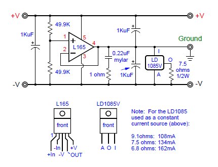
Here is a rail splitter virtual ground circuit which "works", but is a second or third choice sonically. While it does center the virtual ground point perfectly, it requires a constant current source (the LD1085V) hung on its output to sound any good when powering audio circuits. Furthermore, both the L165 and the LD1085V require heat sinks, so this circuit is not good for battery use (too much wasted power).
The L165 comes in a five lead TO-220 package, and is rated for up to 3 Amps at +/-18V.
[/FONT][/SIZE]
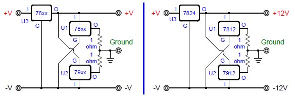
[FONT=Arial,Helvetica][SIZE=-1]Shown here because of their simplicity, the following two circuits use fixed value voltage regulators to create a virtual ground. They MUST have a third voltage regulator (U3) to keep the U1/U2 rail-to-rail voltage from going up or down. Some possible fixed value U3/U1/U2 voltage regulator combinations are: [FONT=Arial,Helvetica][SIZE=-1][+10V, +5V, -5V], [+12V, +6V, -6V], [+18V, +9V, -9V], [+24V, +12V, -12V]. [/SIZE][/FONT]
[/SIZE][/FONT]
[FONT=Arial,Helvetica][SIZE=-1]
Basic Circuit with Fixed Value Voltage Regulators[/SIZE][/FONT]
When a "complimentary pair" of fixed value voltage regulators are used to create a virtual ground this way, the absolute values of their output voltages are each 1/2 of the rail-to-rail voltage. And the rail-to-rail voltage must remain at a set, unvarying voltage which is the sum of the absolute values of both of the rail splitter regulators output voltages. You therefore must use the third voltage regulator (U3).
Without U3, the rail-to-rail voltage could go up or down with load changes, battery drain, as the AC line voltage went up or down, etc. And if the rail-to-rail voltage went up or down, the two fixed value regulators would begin to compete with each other to establish different ground points, one or both constantly wasting current (and possibly overheating or burning up). So U3 is essential to ensure that fixed value regulators U1 and U2 do not interact with each other.
The output of U3 needs to be close to the value of U1 added to the absolute value of U2. As the output voltages of common fixed value voltage regulators vary by as much as 5% from their rated values, buying extra ones and pre-testing them to find their actual output voltages lets you select them to meet the desired U3 = U1 + |U2| .
[FONT=Arial,Helvetica][SIZE=-1]Because U3 consumes twice as much power compared to U1 or U2, a good choice for it is an adjustable voltage regulator such as 3 amp LD1085V or a 5 amp LD1084V. This also gives the advantage of allowing the use of any value fixed voltage regulators for U1 and U2. With an adjustable output voltage regulator for U3, the virtual ground does not have to be centered between the rails. For example, you could make a +5V/-12V split supply by setting the adjustable voltage regulator U3 to 17V, selecting U1 as a 7805 (+5V), and U2 as a 7912 (-12V).
However, it is still a good idea to pre-test U1 and U2 to find their actual output voltages - then adjust the output voltage of U3 (via P1) to meet the the desired U3 = U1 + |U2| before powering up.
[/SIZE][/FONT]
[FONT=Arial,Helvetica][SIZE=-1]Fixed Value Voltage Regulators for Rail Splitter Section Only[/SIZE][/FONT]
[FONT=Arial,Helvetica][SIZE=-1] An alternate way of setting P1 above to the correct voltage is as follows:
1) Insert an ammeter between the +V or -V input and the DC power supply.
2) Set the ammeter on a high scale, such as the 10A scale.
3) Turn on the DC power supply.
4) Quickly adjust P1 to give the lowest quiescent current. If it is below 2A, switch to the 2A scale.
If it is then seen to be below 200mA, (you're aiming for perhaps 5mA to 50mA), switch to the 200mA scale.
5) Then use a voltmeter to test the output voltages relative to the ground point.[/SIZE][/FONT]
[/SIZE][/FONT]
[FONT=Arial,Helvetica][SIZE=-1]
Basic Circuit with Fixed Value Voltage Regulators[/SIZE][/FONT]
Without U3, the rail-to-rail voltage could go up or down with load changes, battery drain, as the AC line voltage went up or down, etc. And if the rail-to-rail voltage went up or down, the two fixed value regulators would begin to compete with each other to establish different ground points, one or both constantly wasting current (and possibly overheating or burning up). So U3 is essential to ensure that fixed value regulators U1 and U2 do not interact with each other.
The output of U3 needs to be close to the value of U1 added to the absolute value of U2. As the output voltages of common fixed value voltage regulators vary by as much as 5% from their rated values, buying extra ones and pre-testing them to find their actual output voltages lets you select them to meet the desired U3 = U1 + |U2| .
[FONT=Arial,Helvetica][SIZE=-1][SIZE=-1][SIZE=-1][FONT=Arial,Helvetica][SIZE=-1][SIZE=-1][SIZE=-1]__________________________ [/SIZE][/SIZE][/FONT][/SIZE][/SIZE][/SIZE][/SIZE][/FONT][FONT=Arial,Helvetica][SIZE=-1][SIZE=-1][SIZE=-1][FONT=Arial,Helvetica][SIZE=-1][SIZE=-1][SIZE=-1]__________________________[/SIZE][/SIZE][/FONT][/SIZE][/SIZE][/SIZE][/SIZE][/FONT]
[FONT=Arial,Helvetica][SIZE=-1]Because U3 consumes twice as much power compared to U1 or U2, a good choice for it is an adjustable voltage regulator such as 3 amp LD1085V or a 5 amp LD1084V. This also gives the advantage of allowing the use of any value fixed voltage regulators for U1 and U2. With an adjustable output voltage regulator for U3, the virtual ground does not have to be centered between the rails. For example, you could make a +5V/-12V split supply by setting the adjustable voltage regulator U3 to 17V, selecting U1 as a 7805 (+5V), and U2 as a 7912 (-12V).
However, it is still a good idea to pre-test U1 and U2 to find their actual output voltages - then adjust the output voltage of U3 (via P1) to meet the the desired U3 = U1 + |U2| before powering up.
[/SIZE][/FONT]
[FONT=Arial,Helvetica][SIZE=-1]Fixed Value Voltage Regulators for Rail Splitter Section Only[/SIZE][/FONT]
1) Insert an ammeter between the +V or -V input and the DC power supply.
2) Set the ammeter on a high scale, such as the 10A scale.
3) Turn on the DC power supply.
4) Quickly adjust P1 to give the lowest quiescent current. If it is below 2A, switch to the 2A scale.
If it is then seen to be below 200mA, (you're aiming for perhaps 5mA to 50mA), switch to the 200mA scale.
5) Then use a voltmeter to test the output voltages relative to the ground point.[/SIZE][/FONT]
[FONT=Arial,Helvetica][SIZE=-1][SIZE=-1][SIZE=-1][FONT=Arial,Helvetica][SIZE=-1][SIZE=-1][SIZE=-1]__________________________ [/SIZE][/SIZE][/FONT][/SIZE][/SIZE][/SIZE][/SIZE][/FONT][FONT=Arial,Helvetica][SIZE=-1][SIZE=-1][SIZE=-1][FONT=Arial,Helvetica][SIZE=-1][SIZE=-1][SIZE=-1]__________________________[/SIZE][/SIZE][/FONT][/SIZE][/SIZE][/SIZE][/SIZE][/FONT]
A 3 terminal fixed value voltage regulator rated for 12V could operate as low as 11.5V or as high as 12.5V.
The LD1085V is an inexpensive ($1), adjustable (1.25V to 28.5V), 3A positive voltage regulator.
The 78xx/79xx, LM317/LM337 voltage regulators are all commonly available and inexpensive (about $0.25).
[FONT=Arial,Helvetica][SIZE=-1][SIZE=-1][SIZE=-1][FONT=Arial,Helvetica][SIZE=-1][SIZE=-1][SIZE=-1]__________________________ [/SIZE][/SIZE][/FONT][/SIZE][/SIZE][/SIZE][/SIZE][/FONT][FONT=Arial,Helvetica][SIZE=-1][SIZE=-1][SIZE=-1][FONT=Arial,Helvetica][SIZE=-1][SIZE=-1][SIZE=-1]__________________________[/SIZE][/SIZE][/FONT][/SIZE][/SIZE][/SIZE][/SIZE][/FONT]
[/FONT][/SIZE]
[FONT=Arial,Helvetica]A Power Op Amp Virtual Ground Circuit[/FONT]
[SIZE=-1][FONT=Arial,Helvetica] Here is a rail splitter virtual ground circuit which "works", but is a second or third choice sonically. While it does center the virtual ground point perfectly, it requires a constant current source (the LD1085V) hung on its output to sound any good when powering audio circuits. Furthermore, both the L165 and the LD1085V require heat sinks, so this circuit is not good for battery use (too much wasted power).
The L165 comes in a five lead TO-220 package, and is rated for up to 3 Amps at +/-18V.
[/FONT][/SIZE]
[SIZE=-1][FONT=Arial,Helvetica]
[/FONT][/SIZE]
[FONT=Arial,Helvetica][SIZE=-1]Power Opamp Rail Splitter
[/SIZE][/FONT]
[/FONT][/SIZE]
[FONT=Arial,Helvetica][SIZE=-1]Power Opamp Rail Splitter
[/SIZE][/FONT]
Note: In the case the schematic images are lost, this page is mirrored at:
A Regulated Virtual Ground Circuit and
Virtual Ground (regulated!) - and Rail Splitter Circuits!
A Regulated Virtual Ground Circuit and
Virtual Ground (regulated!) - and Rail Splitter Circuits!
Last edited:
Could the usual high current (say 5Apk to 10Apk) modification, of adding a parallel transistor to each regulator, be applied to this circuit?
Thanks for posting the schematic. It looks cool, but I'm struggling
to find the fundamental difference to the usual, class AB amplifier-based approach.
While the LM317 tries to keep its output 1.25V above the reference on pin A, an NPN transistor tries to keep its output (=emitter) 0.7V below the reference pin (=base). The same analogy exists between LM337/PNP.
With the usual approach, you use two diodes to generate a bias voltage of 2x0.7V. In your design, you use the 2.5V reference and connect the adjust pins "crosswise" to generate -2.5V. So in the end, this topology is quite close to a class AB amp.
The only difference I see is that in your design, both regulator can source and sink current, while in class AB, the one transistor is doing the sourcing and the other one the sinking.
I'm not sure - probably!Could the usual high current (say 5Apk to 10Apk) modification, of adding a parallel transistor to each regulator, be applied to this circuit?
Well, small current (2-5mA) or large (1500mA), these voltage regulators will constantly output definite voltages 1/2 of the rail-to-rail voltage. That's a different way of operating compared to CL AB or CL B amps, which output ZERO volts unless demanded to DO something. It's really nice having so few components in the VG, the output devices already being 20W TO-220 packages, and all low cost parts.Thanks for posting the schematic. It looks cool, but I'm struggling
to find the fundamental difference to the usual, class AB amplifier-based approach.
While the LM317 tries to keep its output 1.25V above the reference on pin A, an NPN transistor tries to keep its output (=emitter) 0.7V below the reference pin (=base). The same analogy exists between LM337/PNP.
With the usual approach, you use two diodes to generate a bias voltage of 2x0.7V. In your design, you use the 2.5V reference and connect the adjust pins "crosswise" to generate -2.5V. So in the end, this topology is quite close to a class AB amp.
The only difference I see is that in your design, both regulator can source and sink current, while in class AB, the one transistor is doing the sourcing and the other one the sinking.
If we're talking 9v battery power... just use a TC1044 and you're done.
That kind of thing is useless for high power, but for low draw stuff, in the <20mA range, just go with cheap inverter chip like the '1044.
That kind of thing is useless for high power, but for low draw stuff, in the <20mA range, just go with cheap inverter chip like the '1044.
My applications typically start a bit bit higher than 20mA. Also, sonically, I have not been very impressed with charge pump type negative rail generators.
Hi Sonic Wonder
Searching a solution for a stereo solution in the same case with 2 independent power supplies without using 2 transformers I'm digging in virtual grounds because I can't find 4 secondary coils transformers.
I also found your VG schematics at head-fi.org. I'd like to have the audio version work up to +/-18V output. Is there a way to do that keeping the LD1085 or using a 317HV(T) instead would work as fine? An other questions: I see you didn't use the usual protection diodes on the 317/337 (the ones that are paralleled with your R1/R2). And also, the datasheets advise the use of 10µF (higher wouldn't add any better) tantalum caps for your C2/C3 (and TI says tantalum 25µ for your C6 in their equivalent LMS1587-ADJ-CT*) and state equivalent aluminum would be 25 times higher to get the same supply rejection ratio.
*yep: searching this I find LMS1587-ADJ-CT doesn't have the 30Vin limitation, but instead "Maximum Input to Output Voltage (V IN to GND) : 13V" What does this "V IN to GND" means here please?
Some comments please?
Bye bye.
Last edited:
1.3V Across LD1085V
HumNSmoke,
The 1.3V (not 13V) across the LD1085 should have been worded differently as it does not refer to Input to Ground, but rather the minimum voltage drop across that regulator from Input to Output.
I bet you can use other, possibly more modern, voltage regulators with these circuits - so you should try something else in place of the LD1085V if you have it.
My citations are from the Texas' LMS1587 datasheet in "ABSOLUTE MAXIMUM RATINGS" section (page 3). It is really 13V, not 1.3. Further, the dropout is 1.15Vtyp/1.3Vmax for 3A devices as stated at the end of page 4. This 13V may be seen as a power dissipation limitation while it's just a lack of versatility. On the other hand, allowing a huge Vi-Vo would make mandatory to derate a lot the 3A/5A spec. That's why I ask what does this "Vin to ground" means.
Oh I see. 1.5V and 3.3V fixed regulators! Yes, on those specific regulators there is a 13V maximum input-to-ground voltage. That means that your DC input voltage cannot be more than 13V if you use the LM1587 voltage regulators.
But I think you cannot use LM1587 regulators with the "[FONT=Arial,Helvetica][SIZE=-1]Enhanced Virtual Ground for Low Noise Audio[/SIZE][/FONT]" virtual ground circuit, because the LM317/LM337 regulators themselves need a minimum rail-to-rail voltage of about 7.5V, so 1.5V or 3.3V won't cut it..
But I think you cannot use LM1587 regulators with the "[FONT=Arial,Helvetica][SIZE=-1]Enhanced Virtual Ground for Low Noise Audio[/SIZE][/FONT]" virtual ground circuit, because the LM317/LM337 regulators themselves need a minimum rail-to-rail voltage of about 7.5V, so 1.5V or 3.3V won't cut it..
I figured using the -ADJ version. Don't mind, I realized I can use 30Vac transfo to feed a 317HV with 40V and get 36V.
Cool, this alim works great. Summum of elegance design, to get 2 independant supplies from a single 2 secondary coils transformer.
I used a 317HV for U4 and added a 1000µF on its output.
Also, wanting to lower R3/R4, so I first calculated R1/R2 for +/-18V r2r so that Iz would be ~1mA : (36-2,5)/0.001/2=16k75 ~ 16k9 real life. Then I opted for +/-15V and left R3/R4 as are, which make Iz roughly 800µA measured, still enough even knowing Iadj for U1/U2, up to 100µA according 317/337 datasheets, are inside the 800. I used 0.47Ω for R3/R4. Please SonicWonder, can you explain why lowering Iz allows to lower R3/R4 and the aim of these 2 resistors? I couldn't find your reference to John Broskie from your Development Credits. This guy seems to be a heavy writer.
BTW, I think that lowering R3/R4 by 1/4 or 1/2Ω to get nearer to a 0Ω ground impedance... we forget there is yet some Ω before, namely the impedance of the transformer, rectifiers, U4 & U1/U2, so this 1/4~1/2Ω maybe be neglectible isn't it?
Thank you
Last edited:
Thank you for providing the VG1-circuit.
It might be an option for my analog active crossover in a mobile system.
My next project contains 5 dual opamps (maybe it turns out to be 6).
I have quite a list of (noob-) questions:
1.
In the situation where i use single supply class d amps i create virtual ground with the method you can see in the attached pic.
It is quite a simple rail splitter.
What are the main advantages of the VG1 circuit over what i use?
2.
For another system which works with higher voltages i use two 9volt batteries with a center tap.
What are the main advantages of the VG1 circuit over that kind power supply?
3.
What kind of decoupling for the opamps is advised when VG1 is used?
4.
When using two 12V sla batteries the actual voltages that occur during normal use are between 26V and 24V.
My guess is that 5.6K works for R1 and R2 in the VG1 circuit, right?
What type of resistor would be best (metal/carbon, wattage)?
5.
With one or two class d amps on the same supply rail...
Should a LC-filter (maybe 2nd order) at the input be taken into account?
6.
Regarding the capacitor values of C1, C4, C5...
The high quality caps i have in my stock are all chemicon
KZN 2700uF 35V
KZN 4700uF 35V
KZE 470uF 25V
PSG 390uF 25V
PSG 330uF 25V
Which would you advise me to use in which place?
Are the 25V caps a no-go in my case?
7.
Are the 1N4001 in my stock a substitution for D1, D2?
Attachments
Please take a look to
http://www.diyaudio.com/forums/headphone-systems/304015-better-railsplitter-virtual-ground.html
Two options about railspiltter
.
.
.
What are the better way?
http://www.diyaudio.com/forums/headphone-systems/304015-better-railsplitter-virtual-ground.html
Two options about railspiltter
.
.
.
What are the better way?
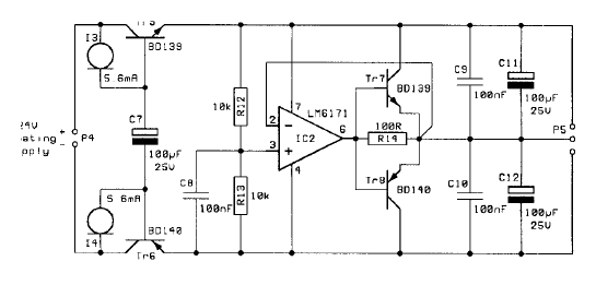
version one (LM6171, BD139, BD140) are from my current headphone amp
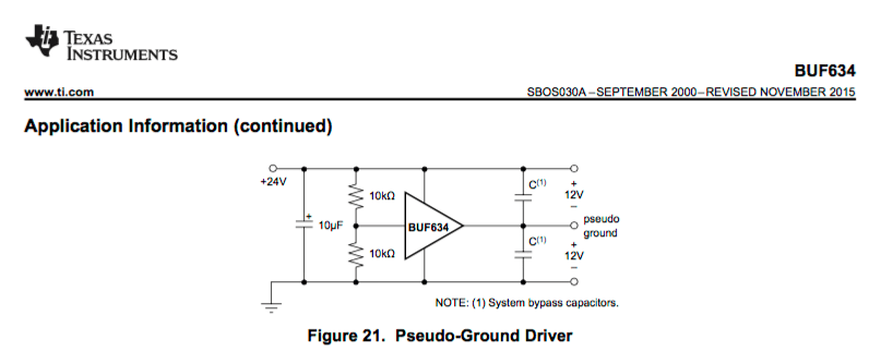
My question - could version two (BUF634) make a better job?
My question - could version two (BUF634) make a better job?
Does anyone know what is the purpose of diodes D3 and D4 in the schematic of VG1 Virtual Ground Circuit on the first post ?
An externally hosted image should be here but it was not working when we last tested it.
In case of catastrophic failure (or wildly asymmetric power-on / power-off), D3 prevents the voltage between +V and Ground from going negative. D4 prevents the voltage between -V and Ground from going positive. The idea is to protect downstream circuitry against reverse bias that might destroy components. For example, Tantalum capacitors.
If your system can deal with the much higher leakage currents of Schottky diodes (see the datasheets, it can be milliamps), using Schottkys for D3 and D4 yields greater protection.
If your system can deal with the much higher leakage currents of Schottky diodes (see the datasheets, it can be milliamps), using Schottkys for D3 and D4 yields greater protection.
- Status
- Not open for further replies.
- Home
- Amplifiers
- Solid State
- Virtual Ground (A Regulated Rail Splitter)