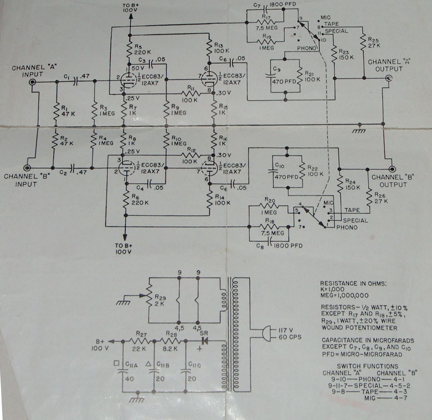
Today it came to my posession a shure stereo conversion preamplifier model M65E.
2 x ECC83 TFK <> tubes, gain 63dB in microphone mode.
My first idea was to change the circuit to a gain of 2 for use as a playstation buffer.
Second idea was to use it as I/V with a 0,68ohm I/V resistor to amplify to 2V.
Do I need the input coupling caps ?
Can I replace the ECC83 with any of E88CC or CCa ?
If it is a 4 x os DAC, does it make sense to use a transformer after 0,68 ohm ?
Any suggestions to improve the circuit ? Bigger output caps ?
Another thing that came to my mind, I read that opamp works best as buffer with no gain. What if the resistor of a standard op amp I/V is changed so that output will only be 2mV instead of 2V ?
Would that be more like a buffer operation ?
Another thing that came to my mind, I read that opamp works best as buffer with no gain.
Where did you read that? I can't think of many things that sound worse than an op-amp operated as a buffer.
Jocko
Hi
I'd leave the unit as is, don't know about the sound but it looks cute.
For IV conversion other tubes suit better, and you coulod consider using a cathode as input.
cheers
I'd leave the unit as is, don't know about the sound but it looks cute.
For IV conversion other tubes suit better, and you coulod consider using a cathode as input.
cheers
For IV conversion other tubes suit better, and you coulod consider using a cathode as input.
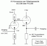
I attach here a scratch. Something like this idea?
Franz
Attachments
Franz G said:
I attach here a scratch. Something like this idea?
Franz
Hi Franz,
Looks good !
I have some suggestions to improve the circuit though:
You may use the same (10k) load on the cathode of the second stage, and tie the supplies of both stages together. Ignoring external load, the power supply now sees "no" current swing.
Some people at the forum may object to the use of the cathode follower at all. Taking the signal from first stage anode will result in some k-ohms output impedance. If that is too high, we still need the CF. Improving the CF includes the use of a current source in the tail, which does away the advantage I describe above.....
Once we are on the subject of current source loading cathodes, also the first stage may be equiped with a CS (instead of the 68 ohm): This greatly reduces distortion
succes
Franz G said:
I attach here a scratch. Something like this idea?
Franz
your I/V resistor is too higher.....the output volts of yours is very stronger 😀 😀
Guido
I agree with Guido for at least 100%.
Best regards,
Audiofanatic 😉
Guido Tent said:
Hi Franz,
Looks good !
I have some suggestions to improve the circuit though:
You may use the same (10k) load on the cathode of the second stage, and tie the supplies of both stages together. Ignoring external load, the power supply now sees "no" current swing.
Some people at the forum may object to the use of the cathode follower at all. Taking the signal from first stage anode will result in some k-ohms output impedance. If that is too high, we still need the CF. Improving the CF includes the use of a current source in the tail, which does away the advantage I describe above.....
Once we are on the subject of current source loading cathodes, also the first stage may be equiped with a CS (instead of the 68 ohm): This greatly reduces distortion
succes
I agree with Guido for at least 100%.
Best regards,
Audiofanatic 😉
Thanks for replies.
Still the question: Can I replace the ECC83 with ECC88 or 81 or 85 or CCa or do they need other anode voltages ?
I would like to just the box to test tubes go - no go ...
Is the 86ohm in Franz's schematic the I/V resistor ?
Why is it bad to use the circuit as is ?
A 0,68 ohm from Iout to gnd would give very little distortion of a 1541.
The box would act like a preamp.
I have completely no knowledge of tube design, only see that three coupling caps at input, between stages and on output.
Still the question: Can I replace the ECC83 with ECC88 or 81 or 85 or CCa or do they need other anode voltages ?
No, as the heather is different: with ECC83 there is 12.6V at pin 4 and 5, at ECC88 it is 6.3V between this pins.
You can find tube datasheets here: http://frank.pocnet.net/sheetsE.html
Some people at the forum may object to the use of the cathode follower at all. Taking the signal from first stage anode will result in some k-ohms output impedance. If that is too high, we still need the CF. Improving the CF includes the use of a current source in the tail, which does away the advantage I describe above.....
Yes, the idea of the CF is keeping the output Z low.
Is the conclusion from your statement: don't use current source for the CF?
Is the 86ohm in Franz's schematic the I/V resistor ?
Exactly, this is at least the intention. Is the value too high, for a TDA1541A?
The value 86ohm is just calculated out of the tube datasheet.
Once we are on the subject of current source loading cathodes, also the first stage may be equiped with a CS (instead of the 68 ohm): This greatly reduces distortion
With a current source instead of the cathode resistor in the first stage, there is a separate I/V conversion resistor needed. Isn't it?
Franz
What about using a LED instead of the first cathode resistor, as I/V converter?
I remember at the triode festival, a speach from Lynn Olson (or was it Morgan Jones?): LED's are very nice low-Z current sources, instead of cathode resistors.
Could this work? Worth a try?
Another question:
Is it recommended to use a coupling cap at the input? Are the 1.3V DC dangerous for the DAC's output?
Franz
So, my idea redrawn would look like this: the LED used as constant current source AND I/V converter 😀
Happily, I designed my DAC board (actually in production) without the I/V conversion, LPF filter and output stage.
So, soon I will have the base to try out different circuits.
Franz
Happily, I designed my DAC board (actually in production) without the I/V conversion, LPF filter and output stage.
So, soon I will have the base to try out different circuits.
Franz
Attachments

Franz G said:No, as the heather is different: with ECC83 there is 12.6V at pin 4 and 5, at ECC88 it is 6.3V between this pins.[snip]
Franz,
I think you can also run the ECC83 heater on 6,3 V between another pin (9?) and 4+5 shorted.
Jan Didden
I think you can also run the ECC83 heater on 6,3 V between another pin (9?) and 4+5 shorted.
Yes, this is possible, it is the situation in the amp from Bernhard.
And the ECC88 has a shield at pin 9.
So, resoldering would be required. And be aware of the different currents, some tubes out of the E88CC family are using. Don't overload the existing tranny.
Franz
... and another idea about current source in the mentioned circuit (should I open a new thread about this ideas?):
Why not use a NiCad accu instead of the LED or cathode resistor?
Very low Z and imho good linearity. The desired voltage delivered.
For this circuit, 15mA load, a 700mAh (or better) NiCad should be good and the accu should never be overloaded.
Franz
Why not use a NiCad accu instead of the LED or cathode resistor?
Very low Z and imho good linearity. The desired voltage delivered.
For this circuit, 15mA load, a 700mAh (or better) NiCad should be good and the accu should never be overloaded.
Franz
Franz:
Morgan Jones is the guru of LEDs. He got me sticking them everywhere in my projects. I've got an amp running in my lab system (soon to be written up) which is an homage to the concept- there's probably 60 LEDs in it. In your circuit, the LED would tend to short out the signal and provide a somewhat nonlinear load.
If you have something like a current-output DAC that has an offset, you can directly couple to a tube cathode, using the DAC to bias the tube. The other way to do I/V with a tube is to pull the current across the cathode resistor with the grid grounded. The DAC sees a load that looks like a parallel combination of the cathode resistor and the looking-in impedance of the cathode (Rload + rp)/(mu + 1). The voltage developed across that combination can be considered the input voltage to the tube.
A 6DJ8/ECC88 can work very well in that topology, but it may take an extra gain stage to get all the way to the standard 2V output.
Hi SY
Thanks for your explanation. So, it's nothing with LED or NiCad's.
But it should work the way, showed below? Maybe not enough output swing, as you mentioned.
I am thinking about including a LPF by a feedback path from the anode to the cathode of the first stage.
Franz
Thanks for your explanation. So, it's nothing with LED or NiCad's.
But it should work the way, showed below? Maybe not enough output swing, as you mentioned.
I am thinking about including a LPF by a feedback path from the anode to the cathode of the first stage.
Franz
Attachments
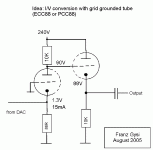
Conceptually it's correct, but your cathode resistor value would need to be adjusted a bit. Remember, the DAC will now be part of the biasing circuit, and it not only pulls across the cathode resistor, it also pulls against the virtual impedance looking in to the cathode.
I haven't used a 1541 in years, but I recall it having a 2mA sink at zero signal. If the tube bias voltage is within the compliance range of the DAC current output, you could get rid of the cathode resistor and let the DAC bias the tube. You'd have to use something other than a ECC88- a high mu tube with low rp would be ideal.
I haven't used a 1541 in years, but I recall it having a 2mA sink at zero signal. If the tube bias voltage is within the compliance range of the DAC current output, you could get rid of the cathode resistor and let the DAC bias the tube. You'd have to use something other than a ECC88- a high mu tube with low rp would be ideal.
Franz G said:What about using a LED instead of the first cathode resistor, as I/V converter?
Could this work? Worth a try?
Another question:
Is it recommended to use a coupling cap at the input? Are the 1.3V DC dangerous for the DAC's output?
Franz
Hi
A LED won't work. You want the current to get into the cathode, not into the bias of the tube. that is why I reccomend the current source for bias.
The resulting input impedance then is 1/gm, where gm of an ECC88 is 10 to 15mA/V. This gives 67 to 100 ohm, which is slightly high.
Another tube like 6C45 or 6H30 could work better (you need high gm for low input Z).
If the DAC is a true current output, 1,3V couldn't harm.
cheers
- Status
- Not open for further replies.
- Home
- Source & Line
- Digital Source
- vintage tube I/V from the year 1960