Bernhard said:Nice to see you guys developing a new tube stage 😀
For a first test I changed the I/V resistor of 1.8 k to 2.7 ohm in a CD650 ( still op amp I/V ) and connected the box to the output of the CD650.
Works so far. Just a little 50Hz noise...
I assume you connected it to the current output of the TDA1541 inside the 650
Just a little 50Hz noise...
This is absolutely normal with vintage gear!
I will try the above descripted idea with 6C45p: 45mA/V will result in input Z of something about 22 ohm.
Disadvantage: a second tube needed for the cathode follower, as the 6C45 is not a double triode.
Franz
Franz G said:
This is absolutely normal with vintage gear!
I will try the above descripted idea with 6C45p: 45mA/V will result in input Z of something about 22 ohm.
Disadvantage: a second tube needed for the cathode follower, as the 6C45 is not a double triode.
Franz
Franz
Have you looked at the required anode resistor ? ith 45 mA/V and 4mA peak current you already have 4V peak with 1 k-ohm
Zout then is yet low, no need for follower.....
The 6C45 needs decent bias though, 20 or 30mA.
succes
Have you looked at the required anode resistor ? ith 45 mA/V and 4mA peak current you already have 4V peak with 1 k-ohm
Not exactly, but I think about 30mA and a anode resistor between 6.6 - 8.3K should do the job.
It is good luck, as I have some 6C45 in my sparebox...
Kind regards
Franz
hi,Franz
the 1st half of ECC88 is a current transmitter,so the 68 ohms resistor is not for I/V ,just is the bias resistor like what Guido Tent said.
the parallel of 10K and Rp of the 1st half ECC88(sorry,I don't know the value of Rp,cause I am not tube guy.....but in my mind, it should be much higher than in the common-cathode state) is for I/V,and the Vout=2ma*Riv
enjoy your DIY
X.G.
Franz G said:
Not exactly, but I think about 30mA and a anode resistor between 6.6 - 8.3K should do the job.
It is good luck, as I have some 6C45 in my sparebox...
Kind regards
Franz
Hi Franz,
But do you agree that 6k8 will give a lot of gain ?
6C45 is a fun tube. use grid stopper by the way........
If the cathode voltage isn't in the cirrect range, you can adapt the bias applying different (from zero) grid voltage. Decouple well.....
succes
But do you agree that 6k8 will give a lot of gain ?
What operating point would you choose?
6C45 is a fun tube. use grid stopper by the way........
... of course! I use already 6C45 as driver for my 300B amp.
First, I complete my DAC and then, in a few days or weeks, I begin to experiment in this direction.
Greetings
Franz
P.S.
Cathode of a 300B as I/V converter here: http://www.tubecad.com/march2001/page6.html
Guido Tent said:
I assume you connected it to the current output of the TDA1541 inside the 650
No, I take it from the cinch output, the only change in the CD650 is 1.8k to 2.7ohm.
Maybe it is not good to have such small signal running through the analog filter and along the muting transistors but it was only a test for the box.
Franz G said:
This is absolutely normal with vintage gear!
It nearly disappears when I disconnect the input cinch cables from the box.
Bernhard said:
No, I take it from the cinch output, the only change in the CD650 is 1.8k to 2.7ohm.
Maybe it is not good to have such small signal running through the analog filter and along the muting transistors but it was only a test for the box.
In that case I am comfortable, in any other case this looks like a weird way of hooking things up.......
Hum may be reduced by inserting a full wave bridge.
cheers
Franz G said:
What operating point would you choose?
Hi Franz
I'd go for 20 to 30mA. You may reduce the anode resistor and subsequently reduce the supply voltage, in order to optimise the gain strucure.
best regards
It nearly disappears when I disconnect the input cinch cables from the box.
In this case: does it appear, when you just connect one chinch cable?
If yes, then cut the shield of the second cable, just before the preamp, avoiding a ground loop.
Franz
Guido Tent said:
In that case I am comfortable, in any other case this looks like a weird way of hooking things up.......
Next step will be skipping the op amp and use passive I/V 2.7 ohm --> analog filter --> cinch out --> box--> Amp
The box sounds soft and lacks bass.
Bernhard said:
The box sounds soft and lacks bass.
yup, typical vintage sound....
transparency won't be great either
Guido Tent said:
yup, typical vintage sound....
transparency won't be great either
It has a gain of 63dB, maybe a little too much...
Also the output cap is only 0.05 µF.
Bernhard said:
Also the output cap is only 0.05 µF.
Yes, those where the days of a little bit of bass......(in spite of 1 M-ohm grid resistors)
Hello
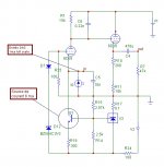
I'm working too on a valves I/U. But I want 0v on input, to avoid stressing my dac wich is based on ad1865.
This is just ideas on paper for the moment...
V1=160V
V2=8V
I : 6ma in first tube, 7ma in CF
Tl431 for negative voltage regulation and as ccs reference.
The 15k resistor on the anode of the first tube gives 15V for 1ma full scale on the ad1865.
The simulation works.
Attachments
Bonjour
Very interesting, I see many similarities:
- cathode input
- DC coupling
- CF
Main difference: you use a current source for the input tube.
What is the purpose of D7 and D12?
Regards
Franz
Very interesting, I see many similarities:
- cathode input
- DC coupling
- CF
Main difference: you use a current source for the input tube.
What is the purpose of D7 and D12?
Regards
Franz
Hello
The diodes keep the grid voltage constant and negative.
In fact, the grid is referenced to the negative voltage with the two diodes (a zener and a normal one : better thermic coeficient).
The negative voltage is referenced to the ground by the tl431.
Like this, the grid is referenced to the ground.
As my input has to be 0V, I have to maintain the grid to a constant negative votage.
I could also put a battery on the grid...
Philippe
- Status
- Not open for further replies.
- Home
- Source & Line
- Digital Source
- vintage tube I/V from the year 1960