Eli,
I am surprised to hear that about JJ's, from most of the people I've talked to I got the impression JJ's were the best available. With the exception of the 'Winged C's'. Sadly, I already have a set of matched JJ EL34's.
Yes, I had intended to use 6U8A's. That's a question you might be able to answer. I'm not crazy about using one of the adapter sockets common for the 7199-6U8A conversion. That leaves me with two options. Use a chassis socket and terminal strips instead of the PC-4. Or, build new circuit boards wired for the 6U8. A friend at work gave me a kit to make circuit boards. Building new boards is an attractive option. Mostly because I could put the components on the bottom with the socket on top. That way I could put the board Under the chassis. Original Dynacos had a cage so the board wasn't too intrusive. But without it the exposed board looks stupid.
I attached an edited diagram. Is the orientation of the diodes correct?
Attachments

No adapters or PCBs, please. The circuitry is simple enough to make point to point wiring easy enough.
If you are lucky, your JJ EL34s are old enough to precede the Octal woes that have set in. If they give you trouble, buy EH "fat bottles" from McShane. Of late, JJ = Jamona Junk. 😡
The bias supply schematic is correct. However, the rail voltage will be approx. 78 V.
If you are lucky, your JJ EL34s are old enough to precede the Octal woes that have set in. If they give you trouble, buy EH "fat bottles" from McShane. Of late, JJ = Jamona Junk. 😡
The bias supply schematic is correct. However, the rail voltage will be approx. 78 V.
Eli,
I would rather do Point to point anyway. Big clumsy fingers. So for Greinacher AC x 5.2 = DC? In that case a 10 volt transformer would be plenty? 10 x 5.2 = 52. Since the spec is only -34 volts.
My JJ KT88's in my Mark VI's and the EL34's are more than a year old.
Thanks again, Kevin
I would rather do Point to point anyway. Big clumsy fingers. So for Greinacher AC x 5.2 = DC? In that case a 10 volt transformer would be plenty? 10 x 5.2 = 52. Since the spec is only -34 volts.
My JJ KT88's in my Mark VI's and the EL34's are more than a year old.
Thanks again, Kevin
For any cap. I/P filter, the rail is (VRMS) (21/2), LESS LOSSES. For the Greinacher circuit, (VRMS) (2.6) is a reasonable approximation.
The bias tap on the Dyna power trafo is at 55 V. The bias rail will be about 70 V. I want to have at least that much available. Greinacher doubling 24 V. will not get there. Use an AnTek AN-0115 in each monoblock.
The bias tap on the Dyna power trafo is at 55 V. The bias rail will be about 70 V. I want to have at least that much available. Greinacher doubling 24 V. will not get there. Use an AnTek AN-0115 in each monoblock.
Last edited:
Thanks Eli,
I just seem to have a lot of problems with too much voltage around here. I'll go wth the AN-0115
kevin
I just seem to have a lot of problems with too much voltage around here. I'll go wth the AN-0115
kevin
Dynaco Mark II/III
Evening All,
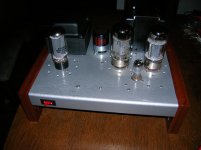
I finished the first Mark II/III, I attached a picture. On my scope the amp starts to clip the top of the wave form at about 64 watts. Below 50 watts it produces well over a 100db on my homemade 12" three ways. (I won't hook them up to the Snells till I've finished the second amp and have played them for a while.)
Meanwhile I think I may have found a use for the Motorola console OPT's. In the Dynaco transformer catalog (down-loadable from Triode) there is the "Low Power High Quality...Amplifier" (figure 3 schematic). It is a beautifully simple amplifier. One 5y3, one 12AX7, and two EL84's.
I think it would be cool to build a pair on a single chassis using a single CD phono input and a dual pot level control for the input to control volume.
The schematic calls for the ultralinear Dynaco A410 OPT. My Motorolas don't have an ultralinear connection. I have seen amps run in triode mode where the output from the screen grid is combined at the OPT end connections via a 100 - 500 ohm resistor. How can I determine the value for this resistor?
And thanks again for any suggestions you might offer, Kevin
Evening All,
I finished the first Mark II/III, I attached a picture. On my scope the amp starts to clip the top of the wave form at about 64 watts. Below 50 watts it produces well over a 100db on my homemade 12" three ways. (I won't hook them up to the Snells till I've finished the second amp and have played them for a while.)
Meanwhile I think I may have found a use for the Motorola console OPT's. In the Dynaco transformer catalog (down-loadable from Triode) there is the "Low Power High Quality...Amplifier" (figure 3 schematic). It is a beautifully simple amplifier. One 5y3, one 12AX7, and two EL84's.
I think it would be cool to build a pair on a single chassis using a single CD phono input and a dual pot level control for the input to control volume.
The schematic calls for the ultralinear Dynaco A410 OPT. My Motorolas don't have an ultralinear connection. I have seen amps run in triode mode where the output from the screen grid is combined at the OPT end connections via a 100 - 500 ohm resistor. How can I determine the value for this resistor?
And thanks again for any suggestions you might offer, Kevin
Attachments
The schematic calls for the ultralinear Dynaco A410 OPT. My Motorolas don't have an ultralinear connection. I have seen amps run in triode mode where the output from the screen grid is combined at the OPT end connections via a 100 - 500 ohm resistor. How can I determine the value for this resistor?
In large measure, the value of the resistor used to tie g2 to the plate is governed by the toughness of g2. The screen grid in EL84s is quite tough and 100 Ω will do. However, since you are going triode mode, wire the sockets for the 6П15П (6p15p), AKA SV83, AKA EL84N, using 1 KOhm resistors to tie the screens to the plates. Sockets wired for the 6П15П work with it and the EL84/6BQ5. 6П15П-EB (ep15p-ev) stock makes a very good sounding triode.
BTW, the low gm 12AX7 can easily run into trouble driving the CMiller of triodes. A pair of 6GK5s will give you both high μ and high gm.
Thanks Eli,
I just did a quick search and cannot find the 6gk5s know of a good source? And since the amp is cathode biased wouldn't I need matched pairs. Could this amp be run as fixed bias?
And is there a brand recomendation for the 6p15p?
Kevin
I just did a quick search and cannot find the 6gk5s know of a good source? And since the amp is cathode biased wouldn't I need matched pairs. Could this amp be run as fixed bias?
And is there a brand recomendation for the 6p15p?
Kevin
Eli,
I found some 6P15P tubes NOS for $1.50 each. I ordered the 17 they had in stock. For $1.50 each I couldn't turn them down.
Kevin
I found some 6P15P tubes NOS for $1.50 each. I ordered the 17 they had in stock. For $1.50 each I couldn't turn them down.
Kevin
Kevin,
Jim McShane is an excellent source for tubes and quite a few parts. The man is a straight shooter. I know Jim has 6GK5s. The SE circuit you plan on following (more or less) has a GNFB loop. So, a matched pair of 6GK5s is unnecessary. The 6GK5 data sheet is here. DON'T omit 1 KOhm Carbon comp. grid stoppers, when employing 6GK5s.
I don't know if Jim has any 6П15П-EB stock. AFAIK, most (all?) 6П15Пs were made at the Voshkhod (Kaluga) plant.
Hey Eli, what about the 6SL7?
The 6SL7 is closely related to the 12AX7. It exhibits a low gm and a high RP. Those are not favorable characteristics for driving the CMiller of triodes.
mr2racer: The 6GK5 is a single triode per bottle, so at least you won't have to sweat over matched sides in the same envelope.
Guys,
When I searched 6FQ5 on eBay I found 8 Hitachi's for $39.00. When I build the amp will I have to put in an AC balance pot if the tubes are not matched?
Kevin
When I searched 6FQ5 on eBay I found 8 Hitachi's for $39.00. When I build the amp will I have to put in an AC balance pot if the tubes are not matched?
Kevin
Not 6FQ5, 6GK5!
If open loop gain is great enough, the closed loop gain in a circuit with GNFB is a function of the feedback network. The 6GK5 is very much a high gain type. So, you will not need a balance control to correct the circuitry. Other factors, such as recording flaws or room effects could require a channel to channel balance adjustment.
If open loop gain is great enough, the closed loop gain in a circuit with GNFB is a function of the feedback network. The 6GK5 is very much a high gain type. So, you will not need a balance control to correct the circuitry. Other factors, such as recording flaws or room effects could require a channel to channel balance adjustment.
Eli,
They were advertised as 6GK5/6FQ5A. Is that not right?
4 NOS Hitachi 6GK5 / 6FQ5A Vacuum Tubes - eBay (item 200562202775 end time Feb-04-11 15:55:29 PST)
So the 1k resistor between the .1 coupling cap and the grid of the output tube is the grid stopper? Also, do you know if any of the other values will change? Especially the cathode resistors? This will be my first cathode resistor floating bias amp. And is it important that they are CC resistors?
Kevin
Last edited:
Hey Everyone,
Just saw the donation heading for the first time. Sorry I didn't notice it sooner.
Can anyone help? I've built the Mark II's and they sound good so far. But the I have a feed back problem. I admit I'm just learning about negative feed back so I hope these questions aren't just a bother.
I'm using Hammond 1650n transformers. I know that the OPT has an effect on feed back. And I think I'm right in that too much feedback results in oscillation. What I have is no effect at all. Because of the design of the transformer outputs I have an 8 and 4 ohm output, but no 16 ohm. So I'm driving the circuit with the 8 ohm. The Mark II uses a 1000 ohm series resistor and a 680 ohm shunt resistor. To tune the circuit I replaced the shunt resistor with a 1k trim pot. Going to both extremes made no difference at all in the sound. So I thought the change from 16 to 8 ohms wasn't leaving me enough voltage. So I dropped the 1k resistor to an 820 ohm. Still no effect.
The feedback is connected between a 680 ohm resistor to the pentode of the preamp tube cathode and a 47 ohm to ground. It then goes on through a 390 pf cap to the screen grid of one of the output tubes.
The question is this. Is it possible these transformers are not affected by feed back? Or do I need to change the values of the cathode resistors on the preamp tube, (680 and 47 ohm)?
Any help would be appreciated.
Kevin
- Status
- Not open for further replies.
- Home
- Amplifiers
- Tubes / Valves
- Vintage power transformers